2 English
IMPORTANT SAFEGUARDS
¤ Read this page carefully to keep your safety.
¤WARNING
· Before mounting or wiring etc., be sure to remove the wire from the battery
minus terminal.
(Not doing so can cause shorts or fires.)
· When extending the ignition, battery, or ground wires, make sure to use
automotive-grade wires or other wires with a 0.75mm² (AWG18) or more to
prevent wire deterioration and damage to the wire coating.
· To prevent a short circuit, never put or leave any metallic objects (such as
coins or metal tools) inside the speaker.
· Abnormal smell In the event the unit generates smoke or abnormal smell,
immediately switch the power OFF. After this, please contact your dealer or
nearest service station as soon as possible.
· Modification Do not attempt to open or modify the unit, for this could
cause fire hazard or malfunction.
· Suffocation After taking the unit out of the polyethylene bag, be sure to
dispose of the polyethylene bag out of the reach of children. Otherwise, they
may play with the bag, which could cause hazard of suffocation.
FCC WARNING
This equipment may generate or use radio frequency energy. Changes or
modifications to this equipment may cause harmful interference unless the
modifications are expressly approved in the instruction manual. The user could
lose the authority to operate this equipment if an unauthorized change or
modification is made.
¤CAUTION
· Do not install the speaker in a spot exposed to direct sunlight or excessive
heat or humidity.
· Water and moisture Do not install the speakers in locations which may be
subject to water or moisture.
· Dust and unstable locations Do not install the speakers in unstable
locations or locations subject to dust.
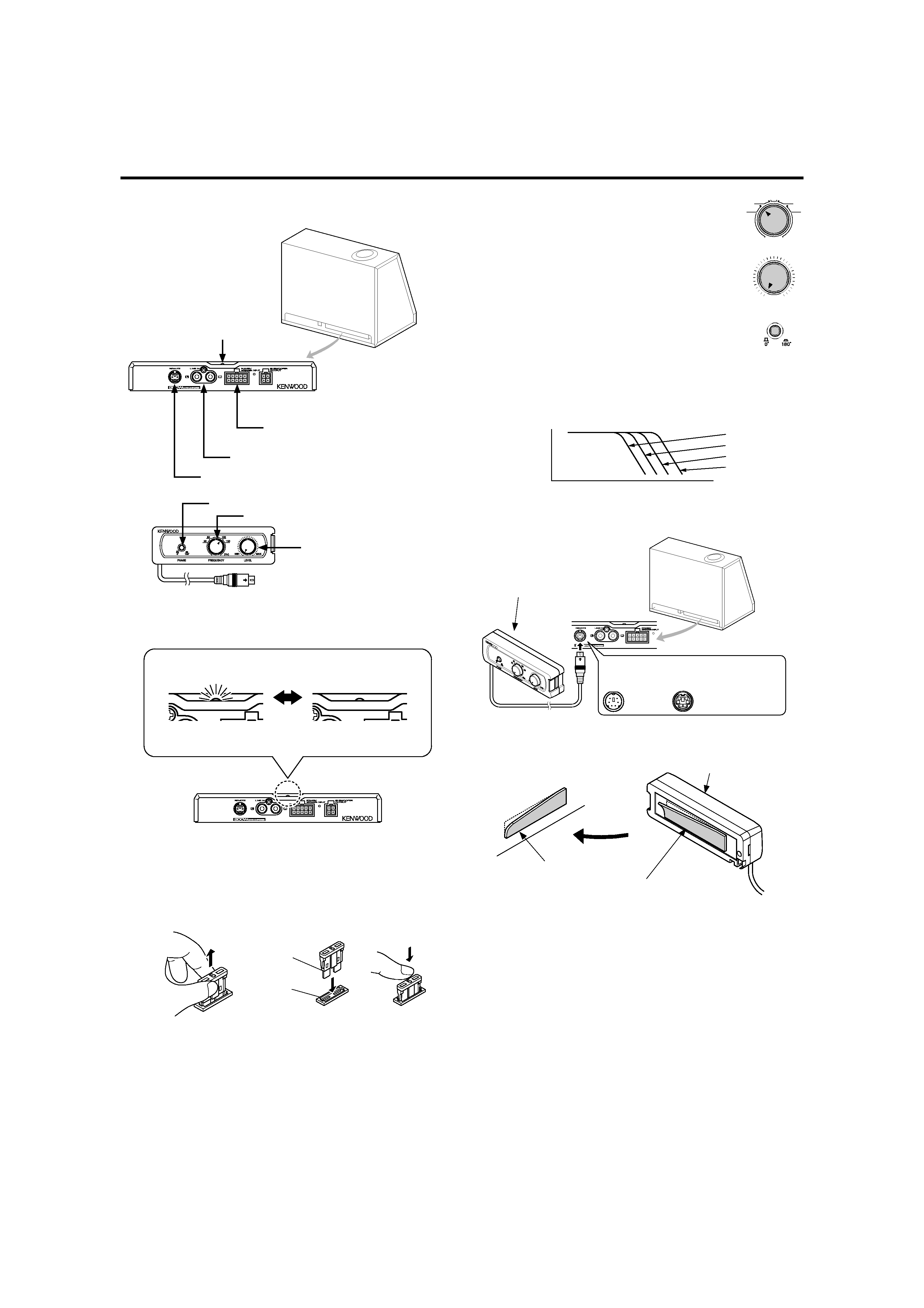
· If the fuse blows, after checking to see if the wiring cord has shorted, be sure
to replace with the stipulated size (amperage) fuse as displayed on the fuse
box.
(Using fuses other than the stipulated size can cause fires.)
To replace the fuse, refer to the vehicle instruction manual.
· To prevent a short circuit when replacing a fuse, disconnect the wiring harness
at first.
· Do not use gasoline, naphtha, or any type of solvent to clean the speaker.
Clean by wiping with a soft, dry cloth.
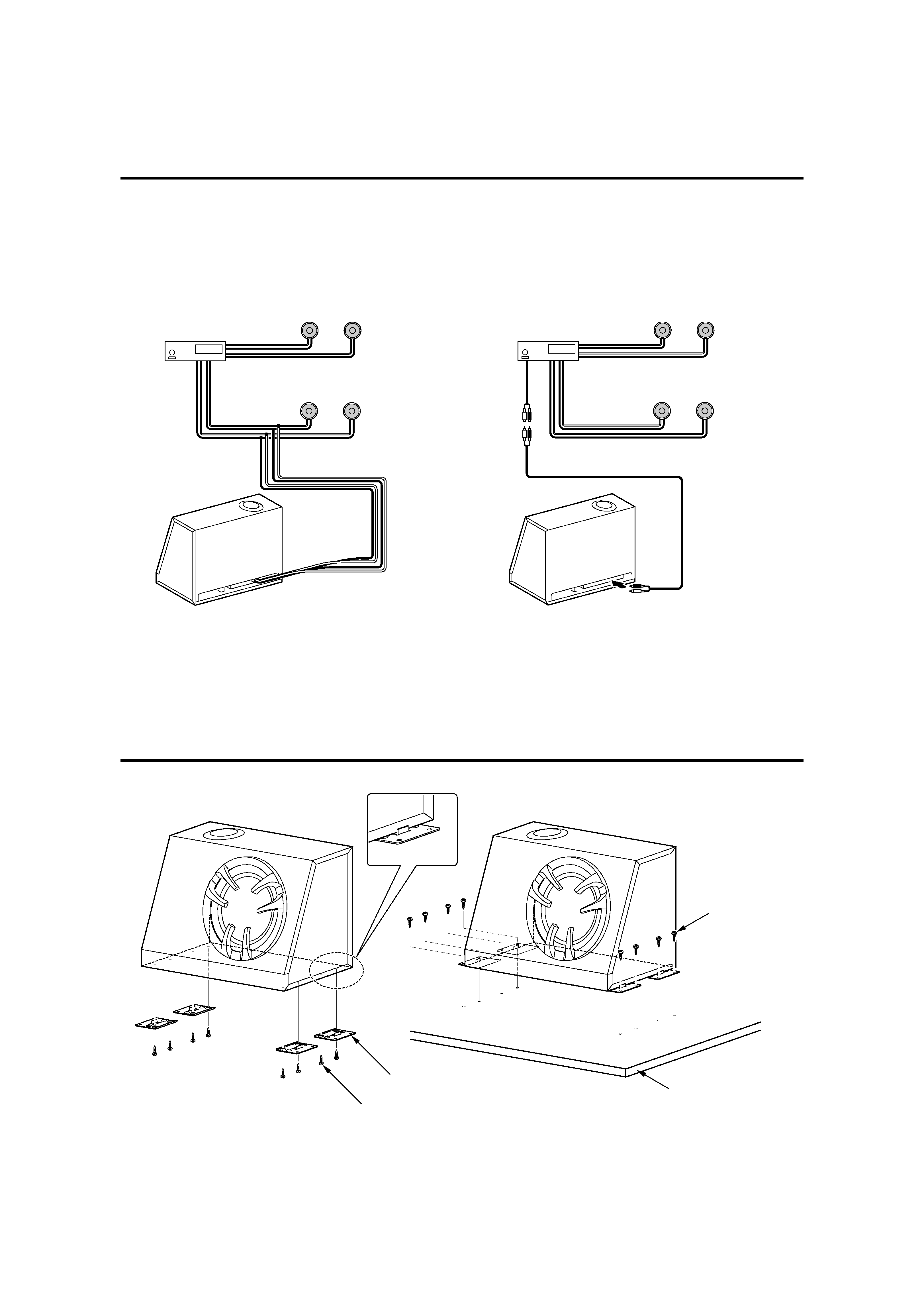
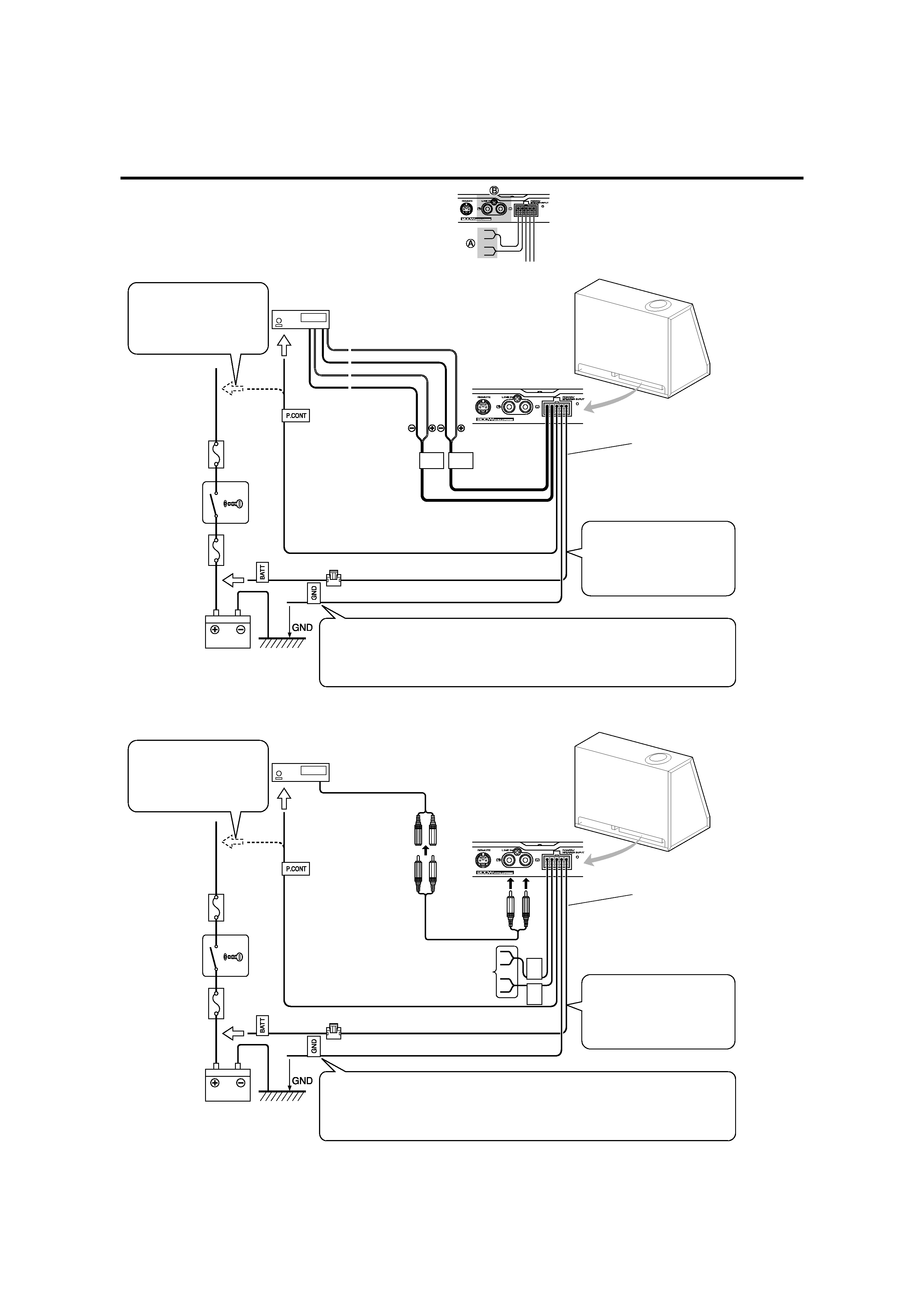
· Do not connect cables and leads to both RCA cable input jacks and the
speaker input terminals simultaneously, for this may cause malfunction or
damage.
· When making a hole under a seat, inside the trunk, or somewhere else in the
vehicle, check that there is nothing hazardous on the opposite side such as
a gasoline tank, brake pipe; or wiring harness, and be careful not to cause
scratches or other damage.
· For ground wire mounting, do not fasten the wire to an airbag, steering or
brake line system or other critical safety unit bolts or nut.
(Can cause accidents.)
· When mounting, be sure to mount in a place that will not interfere with
driving or be dangerous to passengers during sudden braking etc.
(Cause of injury or accidents.)
· After installing the unit, check to make sure that electrical equipment such as
the brake lamps, turn signal lamps and windshield wipers operate normally.
Before installing the speaker or making any connections, please
read all of this instruction manual carefully, to make sure that
you perform these operations correctly.
For your records
Record the serial number, found on the right side of the unit, in the spaces
designated on the warranty card, and in the space provided below. Refer to
this model's name and serial number whenever you call upon your KENWOOD
dealer for information or service on this amplifier.
Model KSC-WD250T Serial number ________
Safety Precautions
In a situation where the car has been left in direct sunlight with its windows
closed and the temperature inside the car has risen to a very high level, switch
on the air conditioner or drive the car for awhile with the windows open before
operating the car stereo. Do not operate the car stereo until the temperature
inside the car has dropped to a normal level.
No.
Part Name
Outside Shape
Quantity
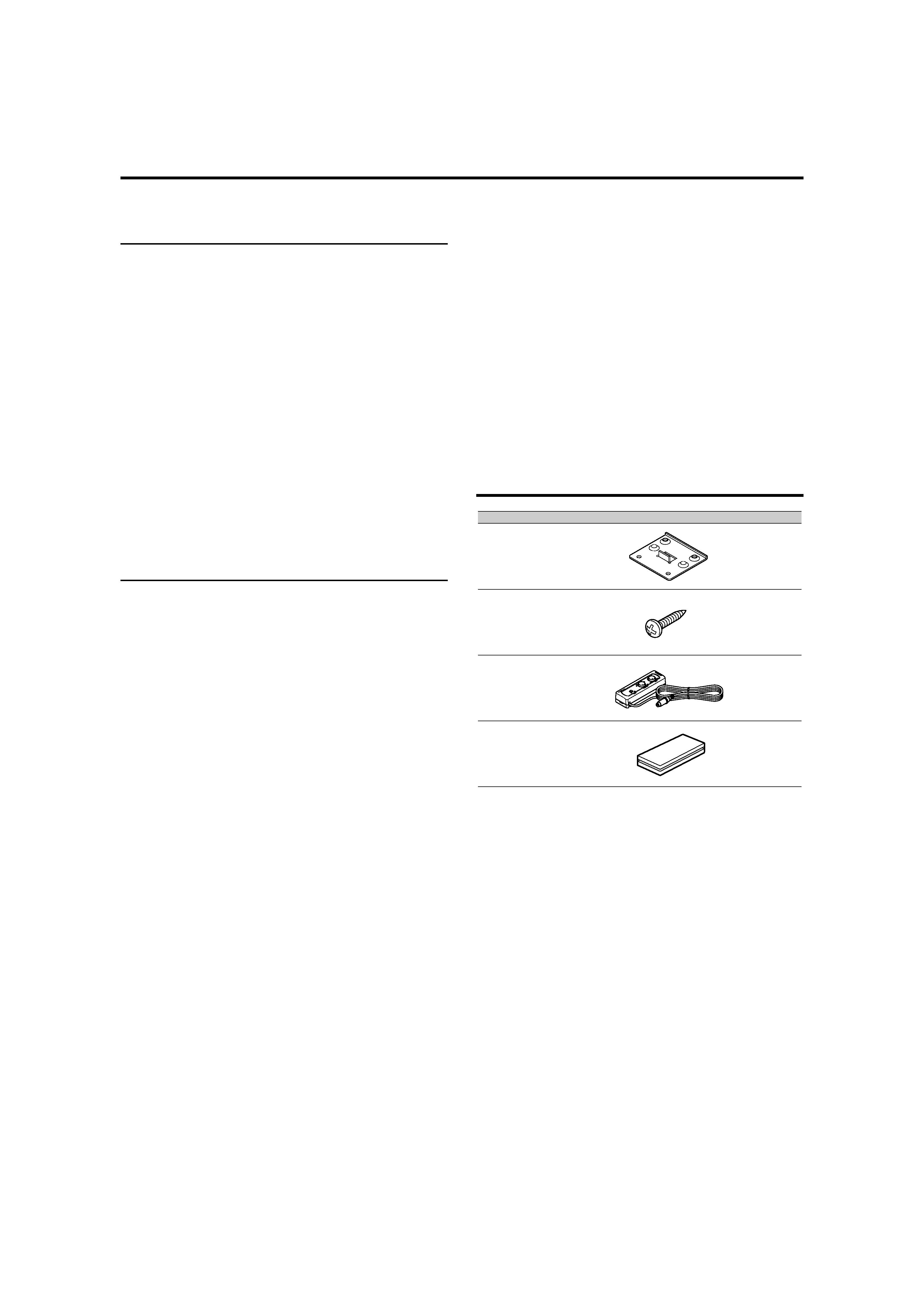
1
Bracket
4
2
Tap screw
(Ø5 × 22mm)
16
3
Remote control unit
(6m)
1
4
Velcro tape
1
Parts included