2
1
1
2
2
3
4
3
1
4
4
4
5
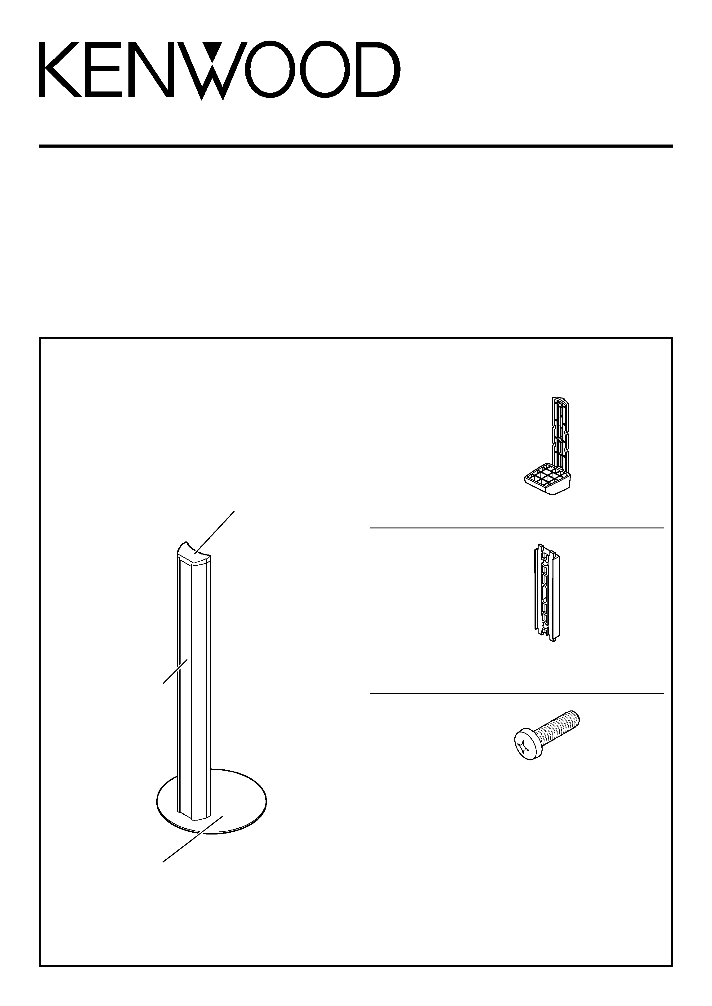
Assembly
The round encircled numerals in the following text refer to
the items listed on the "Accessories" page.
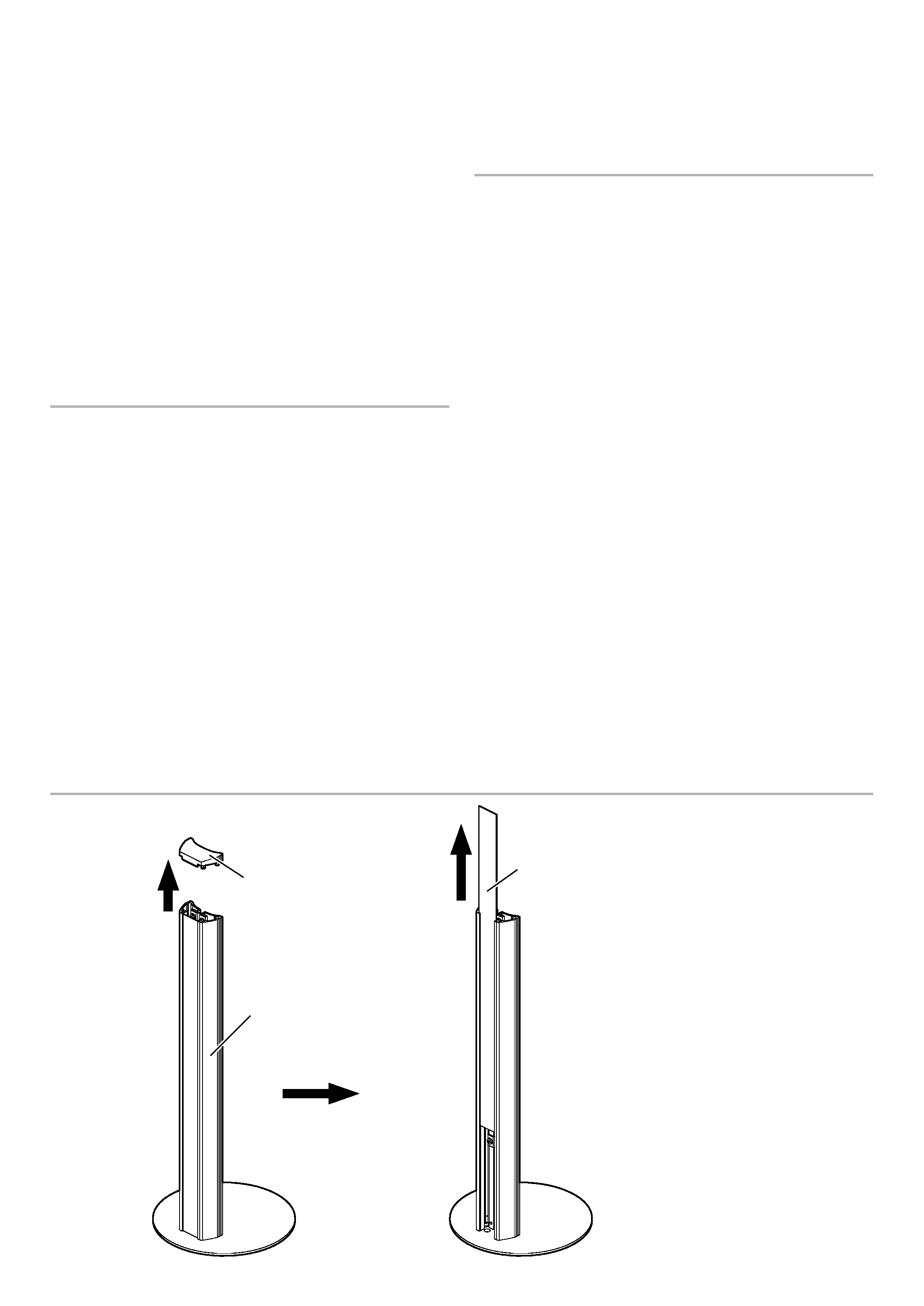
1 Remove the cap and dressing sheet from the pole assembly
1.
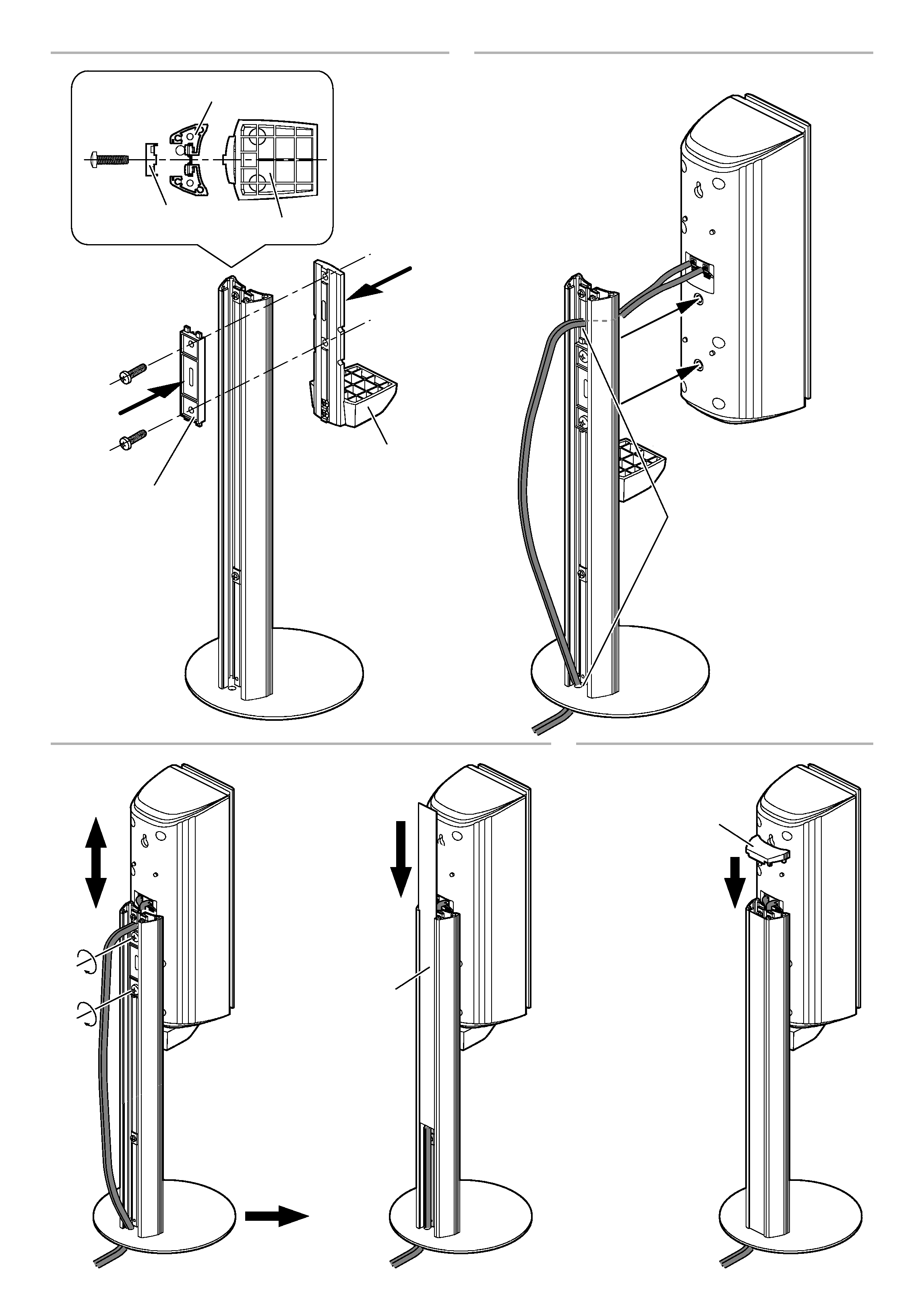
2 Attach holder A 2 and holder B 3 to both sides of the pole
assembly 1 as if sandwiching it, and insert screws 4 into
the holes on the holders through them and the pole as shown
in the figure. Make sure you attach the holders correctly in
the correct orientations. (Do not tighten the screws for the
present.)
3 Distribute the provided speaker wire above the holders, then
through the hole on the bottom plate of the pole assembly
1, and then connect the speaker wire to the terminal on
the speaker. Be sure to observe the polarity of the wire's
conductors and terminals when connecting. Next, insert
screws 4 into the nuts on the rear of the speaker and tighten
them a little so that they clamp the speaker loosely and that
speaker can still be slid up and down.
4 After adjusting the speaker height by sliding it up or down,
clamp the speaker by tightening screws 4 completely. Then,
insert the dressing sheet into the groove on the pole from
above.
5 Attach the cap to the top of the pole .
Note:
Be sure to place the speaker stand in a flat, horizontal place.
Montage
Les numéros entourés d'un cercle qui figurent dans le texte
suivant, se rapportent aux postes de la liste des
"Accessoires".
1 Retirez le cache et l'habillage du montant 1.
2 Fixez le support A 2 et le support B 3 de chaque côté du
montant 1 comme pour le prendre en sandwich, puis
introduisez les vis 4 dans les trous des supports pour
aller dans le montant, comme sur l'illustration. Assurez-
vous que les supports sont fixés dans la direction voulue.
(Ne serrez pas les vis pour le moment.)
3 Faites passer le câble de l'enceinte au-dessus des supports,
puis glissez-les dans l'orifice prévu à cet effet sur la base
du montant 1, et enfin raccordez ce câble d'enceinte à la
borne de l'enceinte. Respectez bien la polarité des
conducteurs du câble et des bornes pour ce raccordement.
Ensuite, introduisez des vis 4 dans les écrous à l'arrière
de l'enceinte et vissez-les légèrement, de façon à ce que
l'enceinte puisse toujours coulisser librement de haut en
bas.
4 Après avoir réglé la hauteur de chaque enceinte en la
déplaçant vers le haut ou vers le bas, assurez leur maintien
définitif en serrant complètement les vis 4. Insérez ensuite
par le haut l'habillage dans la rainure du montant.
5 Fixez le cache sur l'extrémité supérieure du montant.
Remarque:
Installez bien le support d'enceinte à un emplacement horizon-
tal et plat.
Zusammenbauen
Die eingekreisten Ziffern im nachfolgendenText beziehen sich
auf die Komponenten, die auf der "Zubehör"-Seite aufgeführt
sind.
1 Entfernen Sie die Abdeckkappe und die Abdeckleiste von
der Masteinheit 1.
2 Bringen Sie den Halter A 2 und den Halter B 3 an beiden
Seiten der Masteinheit 1 an, und setzen Sie die Schrauben
4 in die Bohrungen der Halter ein, um die Halter an der
Masteinheit festzuschrauben, wie es in der Abbildung
dargestellt ist. Sich vergewissern, daß die Halter korrekt
ausgerichtet sind. (Die Schrauben zunächst noch nicht
festziehen.)
3 Ordnen Sie das mitgelieferten Lautsprecherkabel über den
Haltern an, führen Sie ihn durch die Bohrung in der
Bodenplatte der Masteinheit 1, und schließen Sie danach
das Lautsprecherkabel an die Klemme des Lautsprechers
an. Beachten Sie unbedingt die Polarität der Leiter des
Drahtes und der Klemmen, wenn Sie die Anschlüsse
ausführen. Danach setze Sie die Schrauben 4 in die Muttern
an der Rückseite des Lautsprechers ein, und ziehen Sie diese
Schrauben nur etwas an, damit der Lautsprecher weiterhin
nach oben oder unter verschoben werden kann, und
klemmen Sie anschließend den Lautsprecher provisorisch
fest.
4 Nachdem die Lautsprecherhöhe wie gewünscht eingestellt
wurde, die Schrauben 4 festziehen, um den Lautsprecher
zu fixieren. Danach die Abdeckleiste von oben in die Nut
des Masteinheit einschieben.
5 Die Abdeckkappe am oberen Ende des Masteinheit
anbringen.
Hinweis:
Diesen Stand ausschließlich auf einer flachen, waagerechten
Fläche aufstellen.
Monteren
De omcirkelde cijfers in e volgende tekst verwijzen naar de
onderdelen zoals vermeld op de "Verbindingen" pagina.
1 Verwijder de dop en de sierplaat van het verticale deel van
de standaard 1.
2 Bevestig houder A 2 en houder B 3 aan beide zijden van
het verticale deel van de standaard 1 alsof u dit tussen de
houders klemt en steek schroeven 4 door de gaten in de
houders en door het verticale deel van de standaard zoals in
de afbeelding te zien is. Controleer of u de houders in de
juiste richting bevestigt. (Draai de schroeven voorlopig nog
niet vast.)