5
TEST MODE
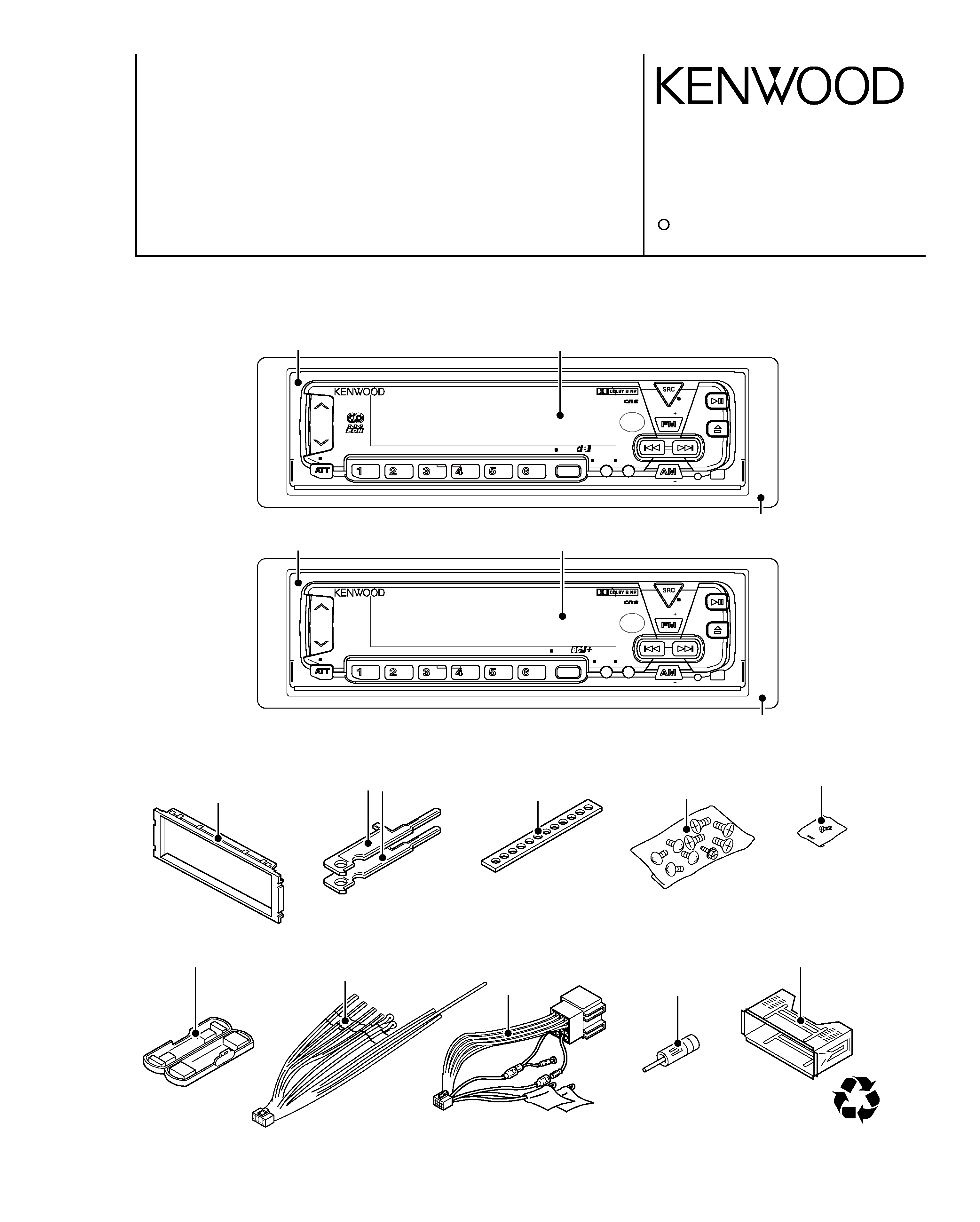
KRC-608,678R/RY/RV/RYV
(1) How to enter the test mode
While holding the FM and Preset 6 keys simultaneously,
reset the unit.
All indicators and display segments are ON at the start of
test mode.
(2) How to exit from the test mode
Reset the unit.
(Note) The test mode cannot be canceled by turning Acc
OFF, power OFF or momentary power down.
(3) (return to beginning)
Pressing the Track Down key jumps to the previous track
to the track being played.
(4) Test mode specification of the tape
o The Blank Skip is initially OFF.
(5) Audio
o The volume is -10 dB (displayed as 30).
o LOUD is OFF, and CRSC is also OFF whether the
function is provided or not.
o With the Bass/Treble and Balance/Fader controls,
pressing the Up/Down key switch the setting alternate-
ly to: Full Boost => Full Cut => Full Boost, Full Right ->
Full Left => Full Right, or Full Front ~> Full Rear =>
Full Front.
o With the high-pass filter, pressing the Up key sets it to
Through/100 Hz/200 Hz and pressing the Down key
sets it to 200 Hz/100 Hz/Through.
o Other adjustments function in the same way as normal
mode.
(6) Backup current measurement
When the unit is reset (backup turned on) while Acc is
OFF or when Acc is turned OFF in test mode, the MUTE
terminal goes on in 2 seconds, instead of 1.5 second.
(The panel, CD, C and MD mechanisms are not activated
at this time.)
(7) Security code registration after E2PROM replacement
servicing (E/M type only)
1. Enter the test mode. (See (1) How to enter the test
mode.)
2. Press the SRC key to set All OFF.
3. Press and hold the AUDIO key for 1 second to enter
menu mode.
4. Press the FM/AM key to select "SECURITY".
5. Press and hold the Track Up/Down for 2 seconds.
6. Enter the code by pressing the Preset 1, 2, 3 and 4
keys.
Example: To enter "3510",
- Press the Preset 1 key 4 times.
- Press the Preset 2 key 6 times.
- Press the Preset 3 key 2 times.
- Press the Preset 4 key once.
7. Press and hold the DISPLAY key for 3 seconds to dis-
play "APPROVED".
8. Quit the test mode (See (2) How to exit from the test
mode.)
(8) How to clear the simple security code (K type only)
1. While the code is requested, press and hold the DISP
key and press and hold the VOL Up key for 3 seconds.
("----" disappears.)
2. Enter "KCAR" from the remote control unit. (Same
operation as the '98 model)
- Press numeric key 5 twice then press the Track Up
key. (This enters "K".)
- Press numeric key 2 three times then press the
Track Up key. (This enters "A".)
- Press numeric key 2 once then press the Track Up
key. (This enters "A".)
- Press numeric key 7 twice then press the Track Up
key. (This enters "R".)
3. The security is canceled and the unit enters the
TUNER mode.
(9) Other
o The DNPP/SBF key of the remote control unit (RC-510)
functions as the menu mode ON/OFF key.
o The OPEN/CLOSE key of the remote control unit (RC-
510) functions as the audio adjustment mode ON/OFF
key.
o The menu is displayed by displaying only the required
features.
o Message such as "CODE OFF" is not displayed when
power is turned ON.
o The contrast can be adjusted only to 0/5/10 using the
Up/Down keys.