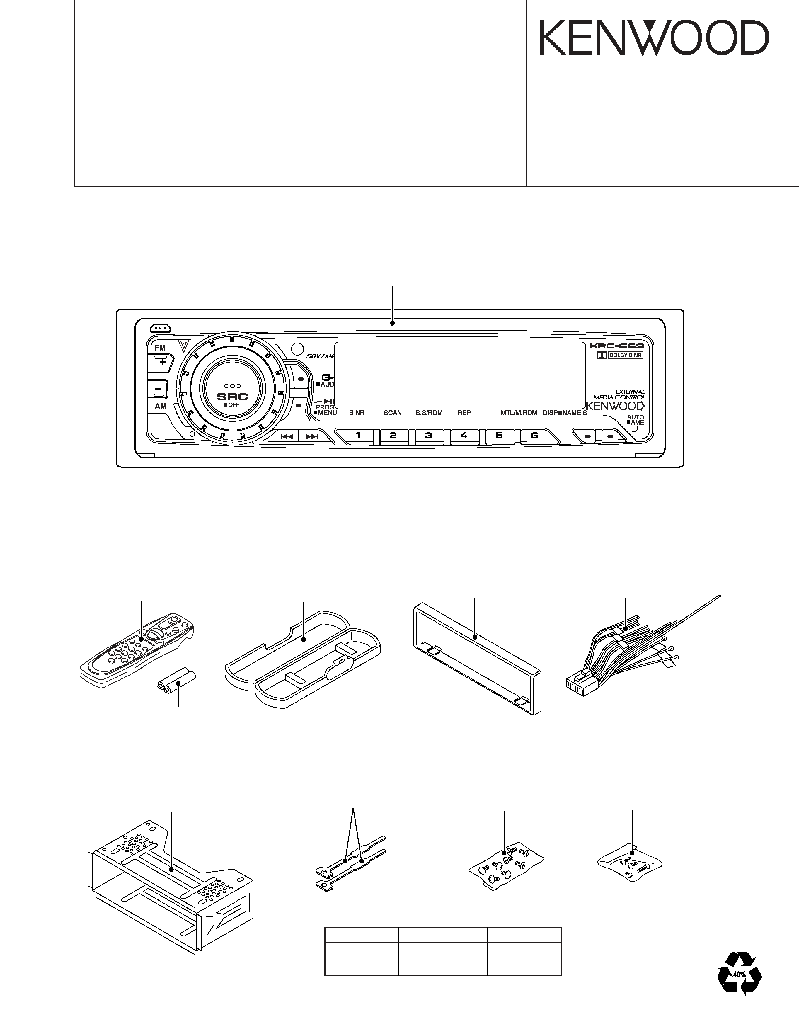
KENWOOD KRC-669 Service Manual

Cover page of KENWOOD KRC-669 Service Manual

Service Manual for KENWOOD KRC-669, downloadable as a PDF file.

We also have owner's manual to this model.

Manual details

  • Immediate download after payment.
  • Delivered as a PDF file.
  • The manual has 28 pages
  • File size: 1.17 MB
  • Available language versions: English
  • Different language versions may vary sligthly in file size and page count.

We guarantee that...

  • our manuals are complete,
  • the manual includes circuit diagrams,
  • our manuals are checked with antivirus,
  • We'll issue refund if the manual is damaged, incomplete or unreadable (our refund policy)

Sample pages

Thumbnail of page 1Thumbnail of page 2Thumbnail of page 3Thumbnail of page 4
Thumbnail of page 5Thumbnail of page 6Thumbnail of page 7Thumbnail of page 8
Thumbnail of page 9
background image
© 2003-11 PRINTED IN JAPAN
B53-0108-00 (N) 429
CASSETTE RECEIVER
KRC-669/669G
SERVICE MANUAL
SIZE AA BATTERY
(Not supplied)
Panel assy
(A64-3199-02) : KRC-669G
(A64-3200-02) : KRC-669
Plastic cabinet assy
(A02-1486-13)
Lever
(D10-4589-04) x2
Screw set
(N99-1730-15)
DC cord
(E30-6322-05)
Escutcheon
(B07-3083-02) : KRC-669G
(B07-3098-02) : KRC-669
Mounting hardware assy
(J22-0011-03)
Screw set
(N99-1719-05)
Remote controller assy
(RC-505)
(A70-2040-05)
TDF PANEL INFORMATION
MODEL
TDF PANEL No.
TDF NAME
KRC-669
Y33-1930-67
TDF-669
KRC-669G
Y33-1930-66
TDF-669G
background image
KRC-669/669G
2
BLOCK DIAGRAM
E2PROM
E-VOL
MPX
&
BUFFER
u-COM
DOLBY EQ
MOTOR
MAIN
AVR
SUB MOTOR
SUB MOTOR
DRIVER
PANEL 5V
EJECT ILLUMI
LCD
EJECT SW
PANEL DET
ROTARY
ENCODER
KEY MATRIX
LCD DRIVER
WITH
RESET SW
REMOCON
P CON
ANT CON
POWER
SUPPLY
IC
SW 5V
RESET
WIRED REMO
ACC DET
SURGE DET
B.U DET
TEL MUTE
BACK UP
TEL MUTE
ACC
SP OUT
POWER
IC
DRIVER
PROTECT
THERMAL
MUTE
PRE MUTE
PRE OUT
IC2
IC9
Q51
Q53
IC11
IC8
IC3
IC6
IC4
IC1
IC2
IC1
PRE MUTE
(REAR)
(FRONT)
PRE OUT
PLL-DATA
PLL-CLK
IFC OUT
AUDIO OUT
S-METER
SW5V
A8V
AM+B
S-METER
AFS
QUAL
MP IN
LEVEL
TAPE
CH
AM
FM
MODE2
MODE3
SUB-
MOT +B
SUB+
MODE1
FOR(L)
FOR(R)
REV(L)
R REEL
F REEL
REV(R)
MTL ON/OFF
DOLBY ON/OFF
MUTE
MS OUT
MS MODE
F/R
SW5V
A8V
BACK UP
SUB-
SUB+
MOT +B
LX REQ M
BACK UP
LX RST
LX MUTE
LX DATA S
LX DATA M
LX CON
LX CLK
LX REQ S
BU5V
I2C
D
A
T
A
I2C
CLK
PANEL
EJECT
ILL
EJECT
REMO
V
OLUME
B
V
OLUME
A
L
D
ATA
L
L
CE
L
D
ATA
S
L
CLK
ILLUMI
BU5V
A8V
FM+B
AM+B
BU5V
ACC DET
B.U DET
PHONE
EN1
EN2
EN3
RST
BEEP
P-MUTE
MUTE
BACK UP
BU5V
SW5V
A8V
DET
FRONT
REAR
SW5V
TUNER
CASSETTE
CH
(X16- )
(X14- )
background image
KRC-669/669G
3
DISASSEMBLY FOR REPAIR
B
B
B
B
A x2
A x2
D
C
E
G
F
H
J
How to Disassemble (PANEL ASSY)
1) Remove four screws (A).
2) While holding the section (B) indicated with arrows, pull and
remove PANEL ASSY.
3) Pull SWITCH UNIT (C) as indicated in the diagram and re-
move knob (D).
(The knob (D) is attached to the rotary with hook (E) and it
is not possible to remove hook (D) only.)
How to install knob (SRC)
1) Place knob (F) and knob (G) in the positions indicated in
the diagram below.
2) While keeping these positions, use a piece of adhesive tape
(H) to hold knobs in position, as shown in the diagarma.
3) Set the rotary (J) position as shown in the diagram.
4) While keeping the letters "SRC" horizontally in position, set
it to the rotary on the panel.
5) Remove the adhesive tape (H).
background image
KRC-669/669G
4
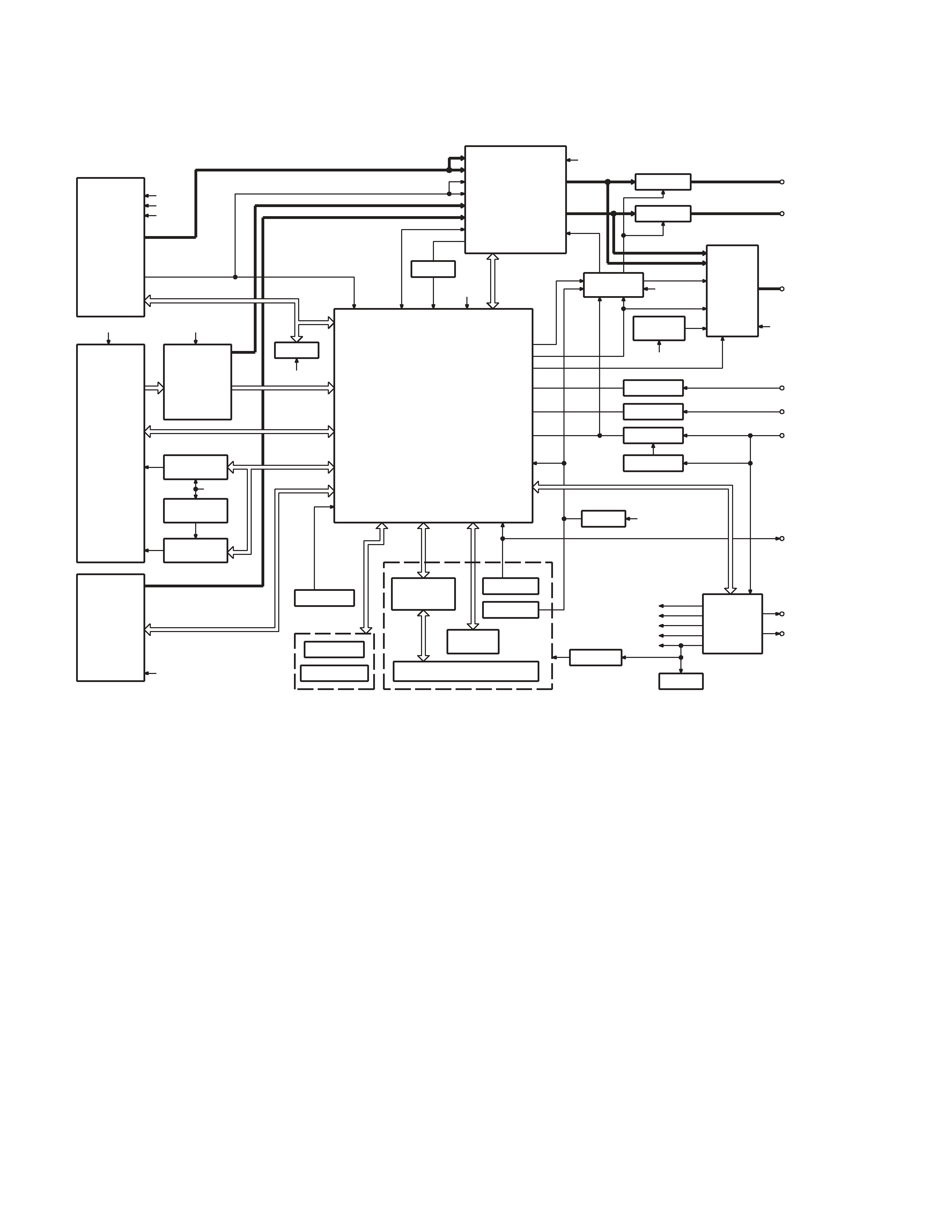
SYNTHESIZER UNIT (X14-9180-24)
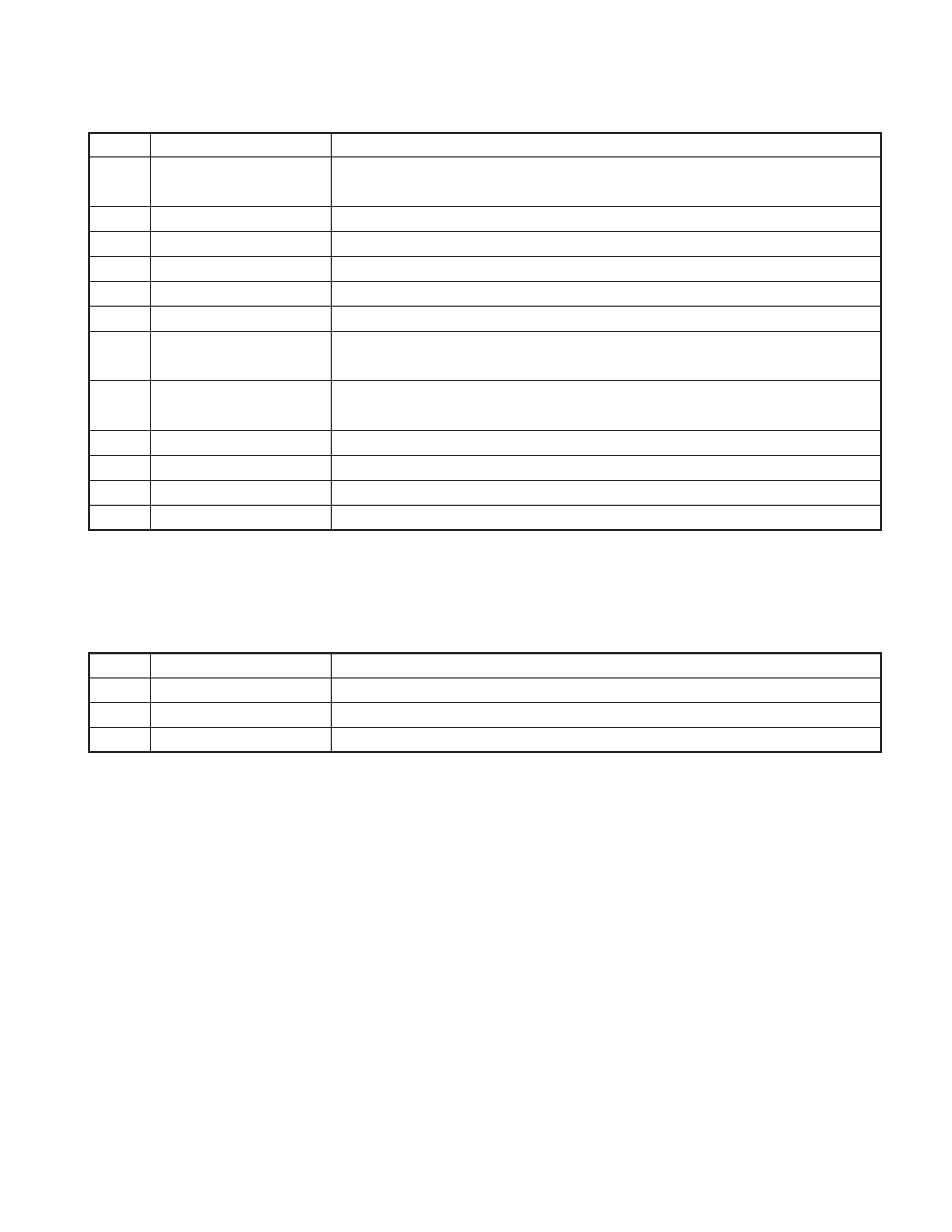
Ref. No.
Application / Function
Operation / Condition / Compatibility
IC1
System
µ-COM
Controls FM/AM tuner, the changer, cassette mechanism, Panel, volume and tone.
IC2
E.Vol & N.C.MPX
Controls the source, volume, tone and FM multiplex detector.
Bu5V (5V), Audio8V (8V), FM+B (8V), AM+B(8V), P-CON, ANT-CON
IC3
Power Supply IC
IC4
Power IC
Amplifies the front L/R and the rear L/R to 50W or 47W maximum.
IC6
Muting logic IC
Controls logic for muting.
IC8
Reset IC
"L" when detection voltage goes below 3.5V or less.
IC9
Equalizer amplifier
Dolby-B, Metal-EQ, Equalizer the Tape sound (120
µsec).
Sub motor control
IC 11
Sub Motor Driver
Q1
Serge Detection
"L" when the back-up voltage becomes more than 18V (momentary power down). "H" when the
back-up voltage becomes less than 18V.
Q2
BACK-UP Detection
"L" when B.u is present. "H" when B.u is absent or momentary power down is detected.
Q3
ACC Detection
"L" when Acc is present.
Q4
SW 5V
ON when the base is "L".
COMPONENTS DESCRIPTION
IN
OUT
EN1
ILLUMI
0V
OFF
5V
ON
IN
OUT
EN2
AM
FM
A8V
0V
OFF
OFF
OFF
2.5V
OFF
ON
ON
5V
ON
OFF
ON
IN
OUT
EN3
ANT-CON
P-CON
0V
OFF
OFF
2.5V
OFF
ON
5V
ON
ON
IN
SUB MOTOR
IN1 (-)
IN2 (+)
LL
STOP
LH
CW
HL
CCW
HH
STANDBY
background image
KRC-669/669G
5
Ref. No.
Application / Function
Operation / Condition / Compatibility
Q5
Power-Antenna
"H" when P-ANT output is short-circuit (P.ANT OFF).
Detection
"L" when FM/AM signal does not exist.
Q6
P-CON Detection
"H" when P-CON output is short-circuit.
Q51
Main Motor SW q
Outputs 14V when the base is "L".
Q52
Main Motor SW w
Q51 turns ON when the base is "H".
Q53
Sub Motor AVR
Output 3.6V when the base of Q4 is "L".
Q54
MSTC SW
ON when the base is "H".
Q151
DSI Driver
DSI lights when the base is "L". DSI turns off when the base is "H". DSI turns on and off when
panel is taken off.
Q152
Panel 5V SW
When the panel is attached, the base goes "L", turning the Tr ON to supply 5V to the panel.
When panel is taken off, panel 5Vcut off.
Q201
Noise buffer
Q350
Pre Mute SW
Drives the Pre Mute sw (Q351~354) when the base is "L".
Q351
Pre Mute SW
Mutes the Rear Lch when the base is "H".
Q352
Pre Mute SW
Mutes the Rear Rch when the base is "H".
SWITCH UNIT (X16-2500-21)
Ref. No.
Application / Function
Operation / Condition / Compatibility
IC1
LCD Driver
Drives LCD
IC2
Remote Control IC
Controls the unit
Q1,4
REMO ON SW
The power supply of IC2 is turned on when base level goes "L".
COMPONENTS DESCRIPTION

Reviews

There are no reviews of this manual yet.