KNA-TM320
3
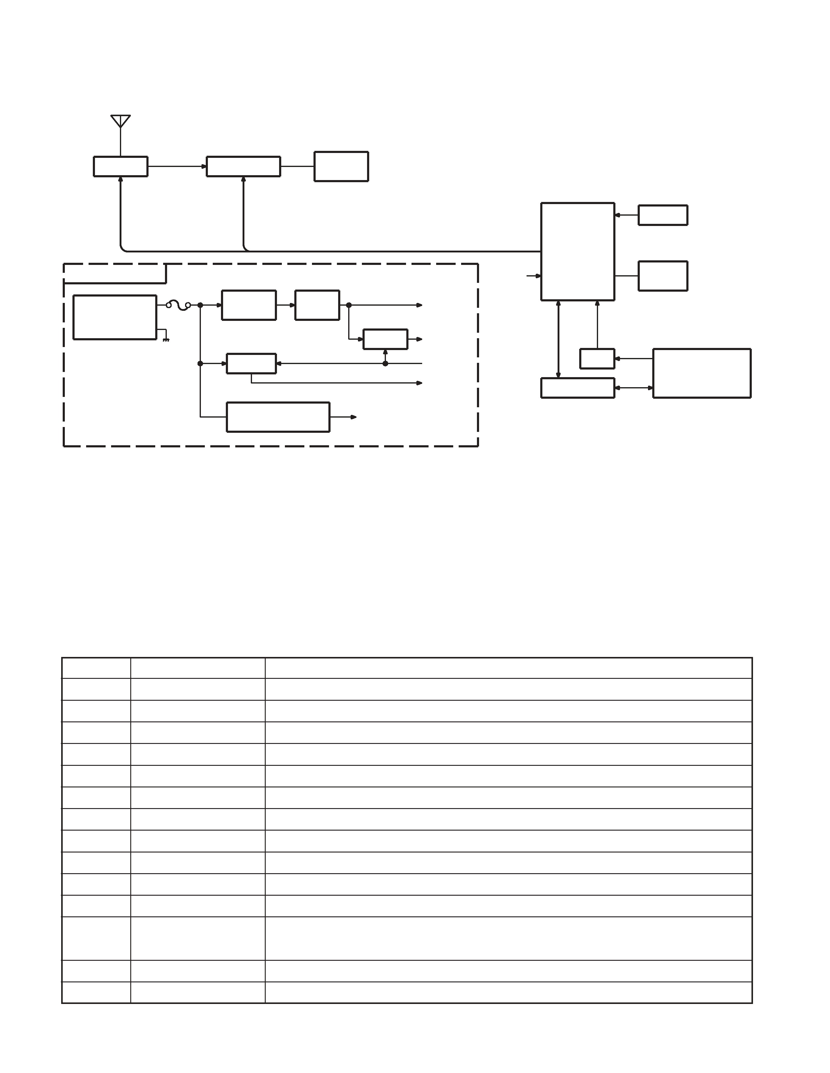
MICROCOMPUTER'S TERMINAL DESCRIPTION
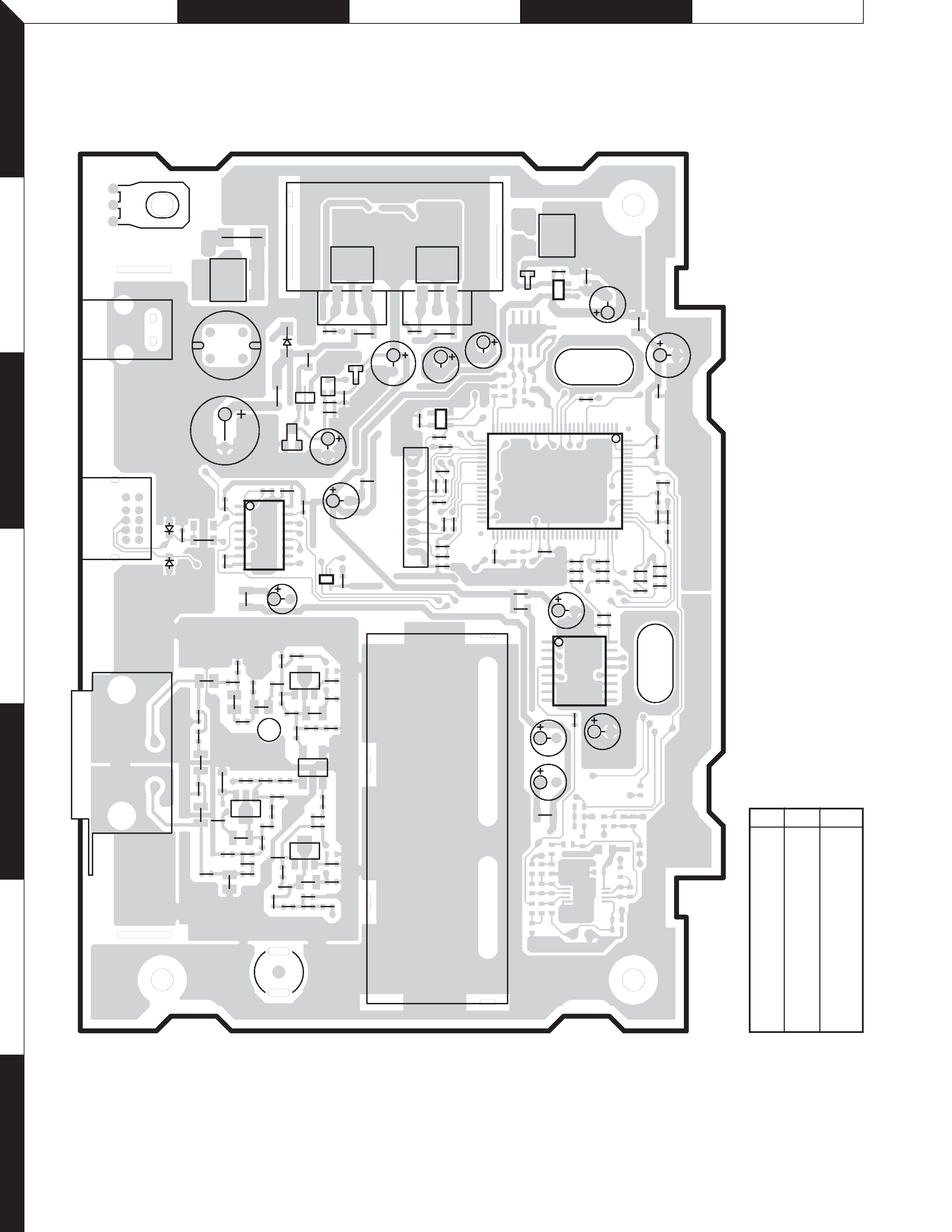
SYSTEM MICROCOMPUTER : M30620FCAFP4Q7 (X25-982 : IC200)
Pin No.
Pin Name
I/O
Function
Processing Operation Description
1-
Not used (N.C.)
2
TMC-ON
O
TMC tuner ON/OFF
Not used (N.C.)
3~7
-
Not used (N.C.)
8
BYTE
I
External data bus width switching input
L : 16 bit, H : 8 bit
9
CNVss
I
Processor mode switching
L : Single chip mode and memory expansion mode,
H : Microprocessor mode
10,11
-
Not used (N.C.)
12
RESET
I
System reset
L : Reset operation
13
XOUT
O
System clock output
System clock output to Xtal
14
Vss
I
Power supply input terminal (GND)
Power supply input terminal (GND)
15
XIN
I
System clock input
System clock input from Xtal
16
Vcc
I
Power supply input terminal (BU5V)
Power supply input terminal (BU5V)
17
NMI
I
NMI external interrupt input
Pull up to BU5V by returning resistor
18,19
-
Not used (N.C.)
20
P-ONIN
I
P-ON Input
L : POW ON, H : POW OFF
21~28
-
Not used (N.C.)
29
SCL
O
I2C clock output
Serial communication clock output
30
SDA
I/O
I2C data output
Serial communication data output
31
F-TXD
O
FLASH I/F data output
Flash microcomputer memory data output terminal
32
F-RXD
I
FLASH I/F data input
Flash microcomputer memory data input terminal
33
FS-CLK
O
FLASH I/F clock output
Flash microcomputer I/F clock output terminal
34
F-BUSY
O
FLASH I/F
Flash microcomputer I/F
35
TXD
O
NAVI communication transmission
NAVI serial communication transmission
36
RDX
I
NAVI communication reception
NAVI serial communication reception
37~40
-
41
F-EPM
I
FLASH I/F
Flash microcomputer I/F
42
-
Not used (N.C.)
43
BU DET
I
BU reduction detection
L : Normal, H : Input voltage (8.5V or less detection)
44,45
-
Not used (N.C.)
46
F-CE
O
FLASH I/F
Flash microcomputer I/F
47,48
-
Not used (N.C.)
49
SYS-ON
O
5V, 8V control
L : 5V, 8V OFF, H : 5V, 8V ON
50,51
-
Not used (N.C.)
52
F-PU
I
Terminal for FLASH write
Pull up input for writing to flash microcomputer
53~59
-
Not used (N.C.)
60
TYPE1
I
Destination selection
Switching for charging
61
TYPE2
I
Destination selection
Switching for market models/OEM
62
Vcc
I
Power supply input terminal +5V
Power supply input terminal (BU5V)
63
-
Not used (N.C.)