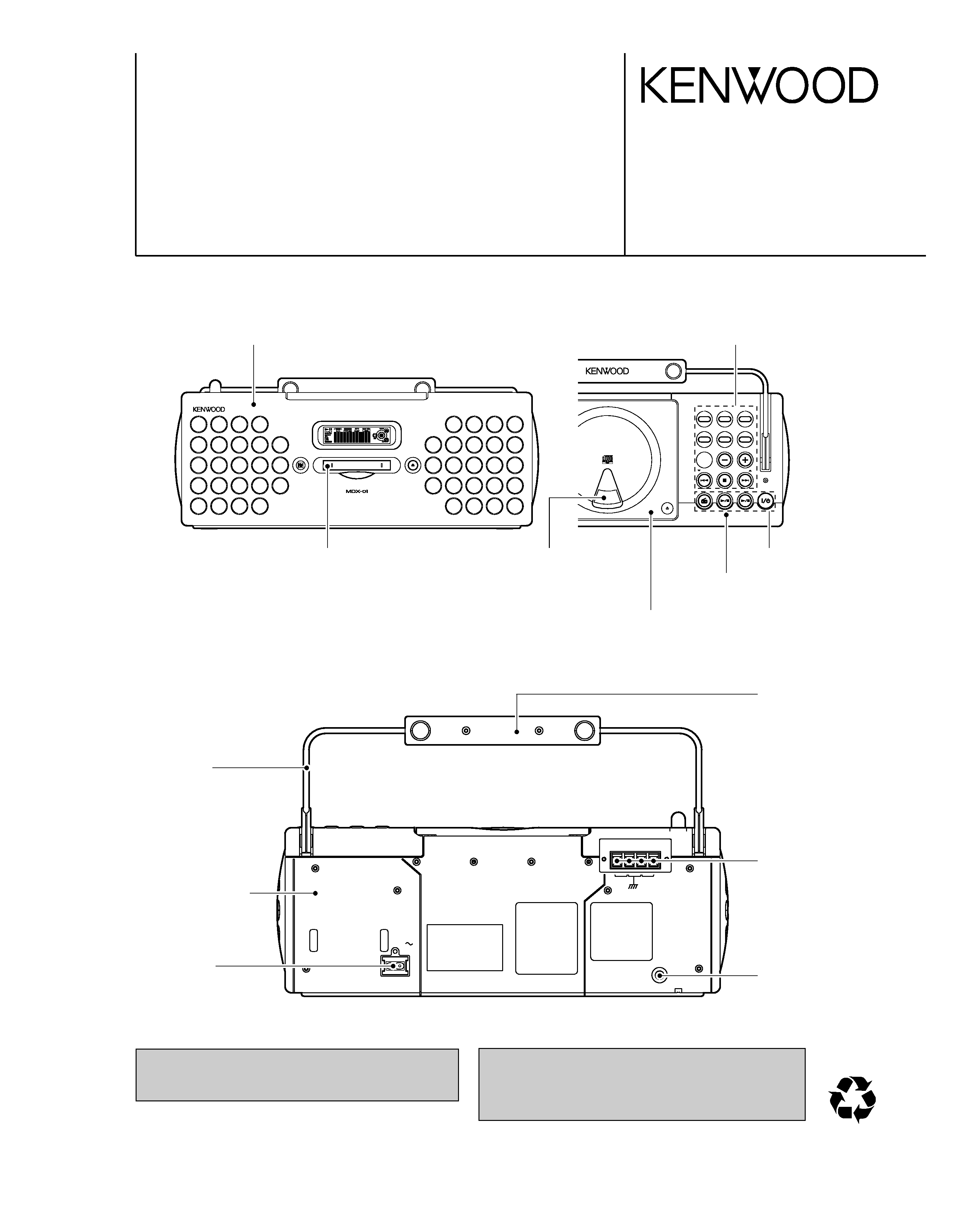
KENWOOD MDX-01 Service Manual

Cover page of KENWOOD MDX-01 Service Manual

Service Manual for KENWOOD MDX-01, downloadable as a PDF file.

We also have owner's manual to this model.

Manual details

  • Immediate download after payment.
  • Delivered as a PDF file.
  • The manual has 30 pages
  • File size: 3.07 MB
  • Available language versions: English
  • Different language versions may vary sligthly in file size and page count.

We guarantee that...

  • our manuals are complete,
  • the manual includes circuit diagrams,
  • our manuals are checked with antivirus,
  • We'll issue refund if the manual is damaged, incomplete or unreadable (our refund policy)

Sample pages

Thumbnail of page 1Thumbnail of page 2Thumbnail of page 3Thumbnail of page 4
Thumbnail of page 5Thumbnail of page 6Thumbnail of page 7Thumbnail of page 8
Thumbnail of page 9
background image
70%
MD PERSONAL STEREO SYSTEM
MDX-01/02
SERVICE MANUAL
© 2000-12/B51-5691-00 (K/K) 332
SOUND
PUSH OPEN
MD REC
REPEAT
VOLUME/MULTI CONTROL
TUNER FM/AM
STANDBY/TIMER
MD
TUNE
MODE
STOP/
CD
MENU
POWER
SET/DEMO
CD
/M
D H
igh
Speed
Dubbing Sy
stem
TUNING
TUNING
MD PERSONAL STEREO SYSTEM
DISC LOADING MECHANISM
EJECT
BEST HITS
Note: Please contact KENWOOD service in your side if
you want to get the AC power cord.
In compliance with Federal Regulations, following are
repro-duction of labels on, or inside the porduct relating to
laser product safety.
KENWOOD-Crop. certifies this equipment conforms to DHHS
Regulations No.21 CFR 1040. 10, Chapter 1, Subchapter J.
DANGER : Laser radiation when open and interlock defeated.
AVOID DIRECT EXPOSURE TO BEAM.
FM 75
9
AM
GND
ANTENNA
ANTENNA
PHONES
AC IN
Front cabinet(OUTER) ass'y
(A60-1942-08): L
(A60-1943-08): R
(A60-1944-08): D
(A60-1946-08): H
(A60-1947-08): S
Knob B
(K29-7900-08)
Knob A
(K27-7893-08): S
(K29-7895-08): L
(K29-7896-08): H
(K29-7898-08): D
(K29-7899-08): R
Top plate R ass'y
(A60-2059-08): DHLR
(A60-2060-08): S
Door
(A52-0914-08): DHLR
(A52-0915-08): S
Door lens
(B12-0408-08): L
(B12-0409-08): R
(B12-0410-08): D
(B12-0412-08): H
(B12-0413-08): S
MD door
(A52-0918-08)
Handle
(K01-0139-08)
Rear cabinet
(A02-2987-08): S
(A02-2988-08): DHLR
AC socket
(E03-0375-08)
Handle(REAR)
(K01-0134-08): L
(K01-0135-08): H
(K01-0137-08): D
(K01-0138-08): R
(K01-0140-08): S
Antenna terminal
(E70-0114-08)
Stereo jack
(E11-0398-08)
D: ORANGE, H: GREY, L: BLUE, R: RED, S: SILVER
background image
AM loop antenna (x1)
(T90-0868-08)
Remote control unit (x1)
(A70-1440-08): DLH
(A70-1441-08): R
(A70-1442-08): S
Battery cover (A09-1191-08)
R6/SUM-3 batteries
AC plug adaptor
(E03-0115-05)
for remote (x2)
RC-
MD
X00
01
AM loop antenna
stand (x1)
(A09-1201-08)
MDX-01/02
2
CONTENTS / ACCESSORIES
CONTENTS / ACCESSORIES .................................. 2
DISASSEMBLY FOR REPAIR....................................3
CIRCUIT DESCRIPTION ............................................4
ADJUSTMENT ............................................................8
PARTS DESCRIPTIONS ............................................9
PC BOARD .............................................................. 10
SCHEMATIC DIAGRAM .......................................... 13
EXPLODED VIEW ....................................................25
PARTS LIST..............................................................27
SPECIFICATIONS ......................................Back cover
Contents
Accessories
Caution on condensation
Condensation (of dew) may occur inside
the unit when there is a great difference in
temperature between this unit and the out-
side.
This unit may not function properly if con-
densation occurs. In this case, leave the
unit for a few hours and restart the opera-
tion after the condensation has dried up.
Be specially cautious against condensation
in a following circumsatance:
When this unit is carried from a place to
another across a large difference in tem-
perature, when the humidity in the room
where this unit is installed increases, etc.
Note related to transportation
and movement
Before transporting or moving this unit,
carry out the following operations.
(1) Remove the CD or MD from the unit.
(2) Press the
6 key of the MD.
(3) Wait for some time and verify that the
display becomes as shown in the figure.
(4) Press the
6 key of the CD.
(5) Wait for some time and verify that the
display becomes as shown in the figure.
(6) Wait a few seconds and turn the unit
OFF.
background image
3
8
4
2
2
1
1
1
1
1
7
1
x3
x2
7 x1
7 x1
10 x1
6 x2
6 x2
5 x2
11
11
11
13
12
12
14
9
x3
MDX-01/02
3
DISASSEMBLY FOR REPAIR
1. How to Remove Front Cabinet
1. Remove 6 screws(
1) from the rear cabinet side.
2. Remove 2 screws(
2) fixed CD and the front
cabinet.
3. Remove 3 screws(
3) from the bottom front side.
4. Move the front cabinet frontwards(
4).
2. How to Remove CD and Top Covers
1. Remove 2 screws fixed CD and top covers(
5).
2. Remove 8 screws fixed the carrying handle
(
6x4) and the rear cabinet(7x4).
3. Turn the antenna cap(
8) to remove and lift the
carrying handle and CD mechanism(
9).
3. How to Remove MD Mechanism
1. Remove the screw(
0) fixed the AC inlet socket.
2. Remove 5 screws fixed the bottom cabinet(
!x3)
and the power transformer(
@x2).
3. Move the main pcb frontwards(
#).
4. Remove 3 screws(
$) fixed the MD mechanism.
background image
MDX-01/02
4
CIRCUIT DESCRIPTION
For more information on each adjustment mode, refer to
each section of 5, "Electrical adjustment".
If other adjustment mode has been entered incorrectly,
press the STOP key to exit the mode.
The number 9 - 13 are not used for service. If these
mode have been entered incorrectly, press the STOP
key immediately to exit the mode. Specially, do not use
EEP INITIAL. (E2PROM data has initialized if used it.)
4. MD TEST MODE FOR ADJUSTMENT
4-1 Entering the Test Mode (MD Mode2)
While pressing the SKIP DOWN key, turn the AC on.
4-2 Cancelling the Test Mode
Turn the AC off.
4-3 Key Operations for Adjustment
No.
LCD
DESCRIPTION
SECTION
1
TEMP ADJU
The work of adjustment is unnecessary
in this mode.
5-5
2
LDPWR ADJU
Laser power adjustment.
5-6
3
LDPWR CHEC
Laser power check.
5-6
4
EFBAL ADJU
Traverse adjustment.
5-7
5
TE B. ADJ
Automatic EF balance adjustment.
-
6
FBIAS ADJU
Focus bias adjustment.
5-8
7
CPLAY MODE
Continuous playback mode.
4-5
8
CREC MODE
Continuous recording mode.
4-6
9
STT-LIMIT
Check the mechanism start limit
switch position.
-
10 JUMP MODE
Track jump checking mode.
-
11 SRV DAT RE
Servo data reading.
-
12
EEP MODE
E2PPROM data reading or rewrite.
-
13
EEP INITIAL
E2PPROM data initializing.
-
KEYS
OPERATION
SKIP UP/DOWN
Select mode or adjustment value change.
MD PLAY/PAUSE
Fix mode or adjustment value.
STOP
Cancel the selected mode.
SKIP UP
Pickup moves outwards when pressed skip up key.
SKIP DOWN
Pickup moves inwards when pressed skip down key.
Remote control only.
4-4 Selection of Adjustment Test Mode
Whenever the [volume/multi-control] knob is turned, the
adjustment test mode is selected.
1. INITIALIZATION
1-1 How to Set Initialization
Insert the power cord to AC outlet with pressing REPEAT
key.
1-2 Operation in Initialization mode
Display shows INITIALIZE, and Standby mode after
mechanism check.
The Display shows error code if mechanism has malfunc-
tion.
The until changes to shipment mode after RAM and back-
up clear, disc out, and so.
2. TUNER PRESET
3-3 Key Function in Test Mode
KEY
CD PLAY
STOP
MENU
SKIP UP
SKIP DOWN
CD MODE
T-SERVO ON(05) u
w
T-SERVO OFF(03)
Stop to CD operation(01)
HI SPEED(double speed) u
wNOR
SPEED: in playback
Playback in STOP mode.
Track up of CD.
FF search of CD if key pressed
more 400ms.
Pickup move outwards in STOP
mode if key pressed more 400ms.
Playback in STOP mode.
Track down of CD.
FB search of CD if key pressed
more 400ms.
Pickup moves inwards in STOP
mode if key pressed more 400ms.
MD MODE 1
­
Stop to operation.
Change to mute-off.
Choose the REC input;
digital or analog in stop
mode.
Track up of MD.
FF search of MD if key
pressed more 400ms.
Track down of MD.
FB search of MD if key
pressed more 400ms.
3. TEST MODE
3-1 TEST Mode Setting
TEST MODE
SETTING
CD
MD REC
MD 1
SKIP UP
Insert the power cord
FTC & Sub-Clock
to outlet with pressing
Oscillation Check
BEST HITS
every left key
Mode
MD mode2
SKIP DOWN
FTC&Sub-Clock Oscillation Check Mode
FTC test mode is after Sub-Clock Oscillation Check
Mode(Internal Oscillation, Check of Period) Check Mode
is 5 times maximum. FTC carries if 1 tlme OK.
The unit is STOP mode after display shows error if 5
times NG.
No Oscillation îERR 1
Period NGîERR 2
(FTC mode is factory use only)
3-2 Test Mode Cancel
The unit cancel the test mode after initialization if pull out
power cord.
The unit cancel the test mode after no initialization if
power off.
Error Code
CD
In 1st figure "C"
MD
In 3rd figure "M"
CD Door SW
In 7th figure "S"
P.CH BAND
FREQ.
P.CH BAND
FREQ.
1
FM
98.30 MHz
21
AM
531 kHz
2
FM
87.50 MHz
22
FM
87.50 MHz
3
FM
89.10 MHz
23
FM
87.50 MHz
4
FM
108.00 MHz
24
FM
87.50 MHz
5
FM
90.00 MHz
25
FM
87.50 MHz
6
FM
87.50 MHz
26
FM
87.50 MHz
7
FM
87.50 MHz
27
FM
87.50 MHz
8
FM
87.50 MHz
28
FM
87.50 MHz
9
AM
1602 kHz
29
FM
87.50 MHz
10
AM
999 kHz
30
FM
106.00 MHz
11
AM
630 kHz
31
FM
87.50 MHz
12
AM
1440 kHz
32
FM
87.50 MHz
13
FM
106.00 MHz
33
FM
87.50 MHz
14
AM
531 kHz
34
FM
87.50 MHz
15
FM
87.50 MHz
35
FM
87.50 MHz
16
FM
98.00 MHz
36
FM
87.50 MHz
17
FM
98.50 MHz
37
FM
87.50 MHz
18
FM
87.50 MHz
38
FM
87.50 MHz
19
AM
990 kHz
39
FM
87.50 MHz
20
FM
97.70 MHz
40
AM
945 kHz
TB/FB (07)
In STOP mode.
Selfcheck result shows
2 figures
TG/FG (08)
FE/RF (09)
TE/VC (10)
background image
MDX-01/02
5
CIRCUIT DESCRIPTION
1. Setting of Continuous Playback Mode
No.
Key
1
4 ¢
Select [CPLAY MODE]
2
Load disc
3 PLAY
[CPLAY MID]
[c=xxxx a=yy] error
(xxxx=C1 error, yy=ADIP error)
[CPLAY OUT]
[c=xxxx a=yy] error
(xxxx=C1 error, yy=ADIP error)
4 STOP
[CPLAY MODE]
2. Change of Playback Points(in continuous playback mode)
No.
Key
Display/Function
Display/Function
1
PLAY
2
[CPLAY IN]
[c=xxxx a=yy] error
(xxxx=C1 error, yy=ADIP error)
PLAY
3
Carry out No.1 to 3 in the above table.
4
5
STOP
[CPLAY MODE]
EJECT
Disc out
1. Continuous Recording Setting
No.
Key
Display/Function
1
4 ¢
Select [CREC MODE]
2
Load the recordable disc
3 PLAY
[CREC MID]
4 PLAY
[CREC (zzzz)] CREC address
(0300h cluster=recording start point)
5 STOP
[CREC MODE]
2. Change and End of Recording Points
1
Carry out No.1 to 3 in the above table Select[CREC MID]
2
¢
[CREC OUT]
3 PLAY
[CREC (zzzz)] CREC address
(0700h cluster=recording start point)
4 STOP
[CREC MODE]
6
5
¢ (2time) Select [CREC IN]
7 PLAY
[CREC (zzzz)] CREC address
(0300h cluster=recording start point)
8 STOP
[CREC MODE]
PLAY
[CREC MID]
9 EJECT
Disc out
1. The recording start addresses of IN, MID, and OUT are
described below.
IN
30H cluster
MID 300H cluster
OUT 700H cluster
2. An erasure prevention control is not detected in the test
mode. Be careful not to enter the continuous recording
mode using a disc containing the data that should not be
erased.
3. Do not record continuously for more than five minutes.
4. Take care that no vibration is applied during continuous
recording.
5. ELECTRICAL ADJUSTMENT
5-1 Precaution during confirmation of Laser
Diode emission
During adjustment, do not view the emission of a laser
diode from just above for confirmation. This may dam-
age your eyes.
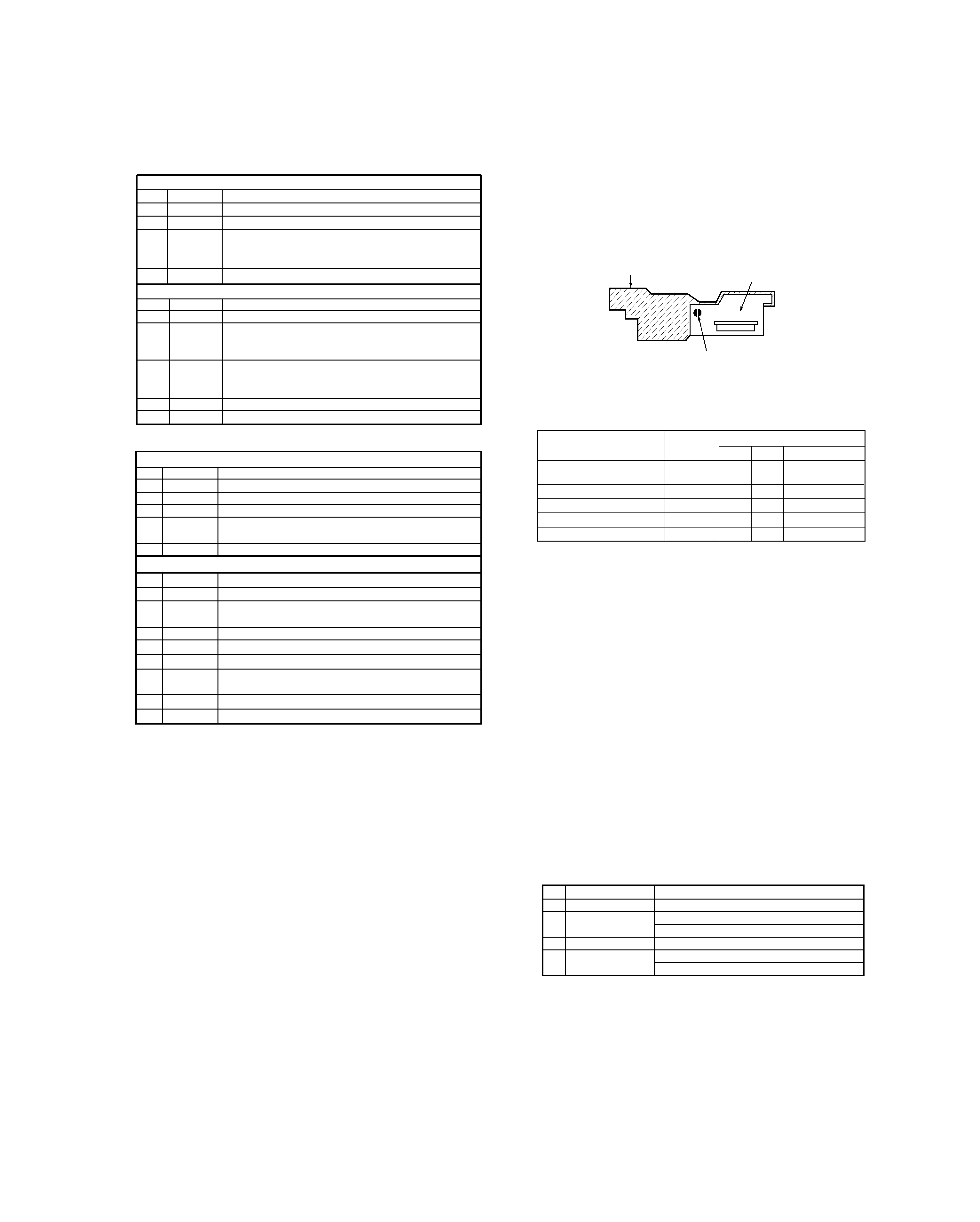
5-2 Precaution on handling of Optical pick-up
(KMS-260B)
The laser diode in an optical pick-up is easy to be sub-
ject to electrostatic destruction. Therefore, solder-
bridge the laser tap on the flexible board when han-
dling the optical pick-up.
4-5 Continuous Playback Mode
4-6 Continuous Recording Mode
When removing the flexible board from the connector,
make a solder bridge in advance, then remove the
board. Be careful not to remove the solder bridge before
inserting the connector. Moreover, take careful mea-
sures against electrostatic destruction. The flexible
board is cut easily. Handle the flexible board with care.
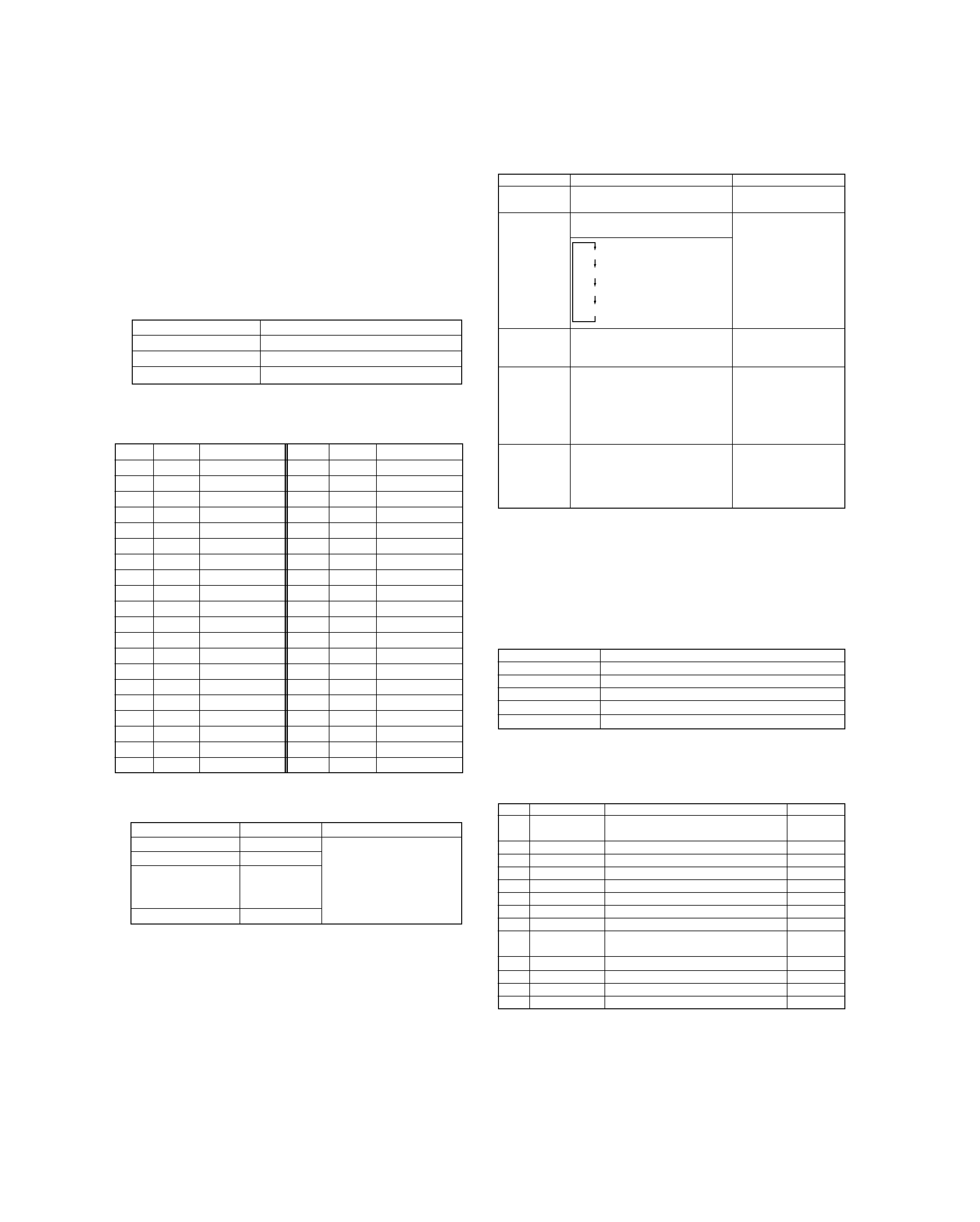
5-3 Precaution during adjustment
1) Perform the adjustment and confirmation marked with "O"
in the order shown in the table when the parts below are
replaced.
2) In the test mode, perform the adjustment. After adjust-
ment is completed, cancel the test mode.
3) Perform the adjustment in the order described.
4) Use the following tools and measurement equipment.
· CD test disc TGYS-1
· Laser power meter
· Oscilloscope (with bandwidth of more than 40 M
)
(Calibrate the probe before measurement.)
· Digital voltmeter
· Thermometer
5) Take care that VC and GND (ground) are not connected
on the oscilloscope when two or more signals are moni-
tored on the oscilloscope. (VC and GND are short-circuit-
ed in this case.)
5-4 Creating the recordable continuous recording
disc
This disc is used for focus bias adjustment and error rate
confirmation. How to create the recordable continuous
recording disc is 4-6.
Optical
BD board
pick-up
IC6
D101
IC1,IC2,IC10
1.Temperature compen-
sation offset adjustment
X
O
O
O
2.Laser power adjustment
O
O
X
O
3.Traverse adjustment
O
O
X
O
4.Focus bias adjustment
O
O
X
O
5.Error rate confirmation
O
O
X
O
Pick-up
Flexible board
Laser tap
5-5 Offset Adjustment
No.
Key
Display/Function
1
4 ¢
Select [TEMP ADJU]
2 PLAY
[TEMP=xx (yy)]
(xx=compensation data, yy=setting temperature)
3
4 ¢
Input "yy" with present temp..
4 PLAY
[TEMP=
SAVE] in writing data
[TEMP ADJU ST]
5-6 Laser Power Check and Adjustment
Laser power setting in playback and recording modes.
Preparation
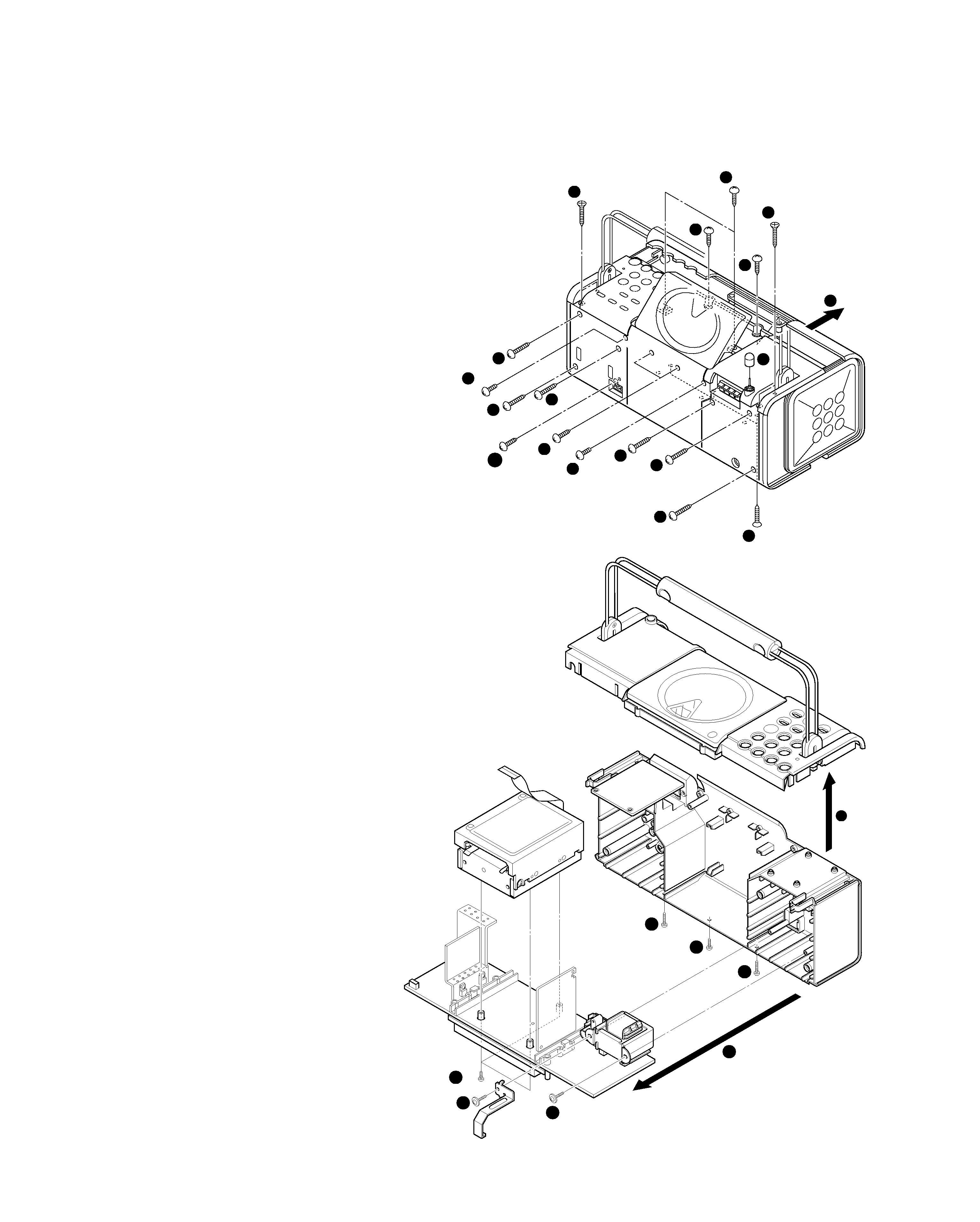
1. Remove the MD mechanism from the unit.
2. Connect the digital voltmeter to IOP1 and 2 on X33 pcb.
3. Remove the top plate from traverse unit.
4. Remove the magnetic head.
5. Remount the MD mechanism to the unit

Reviews

There are no reviews of this manual yet.