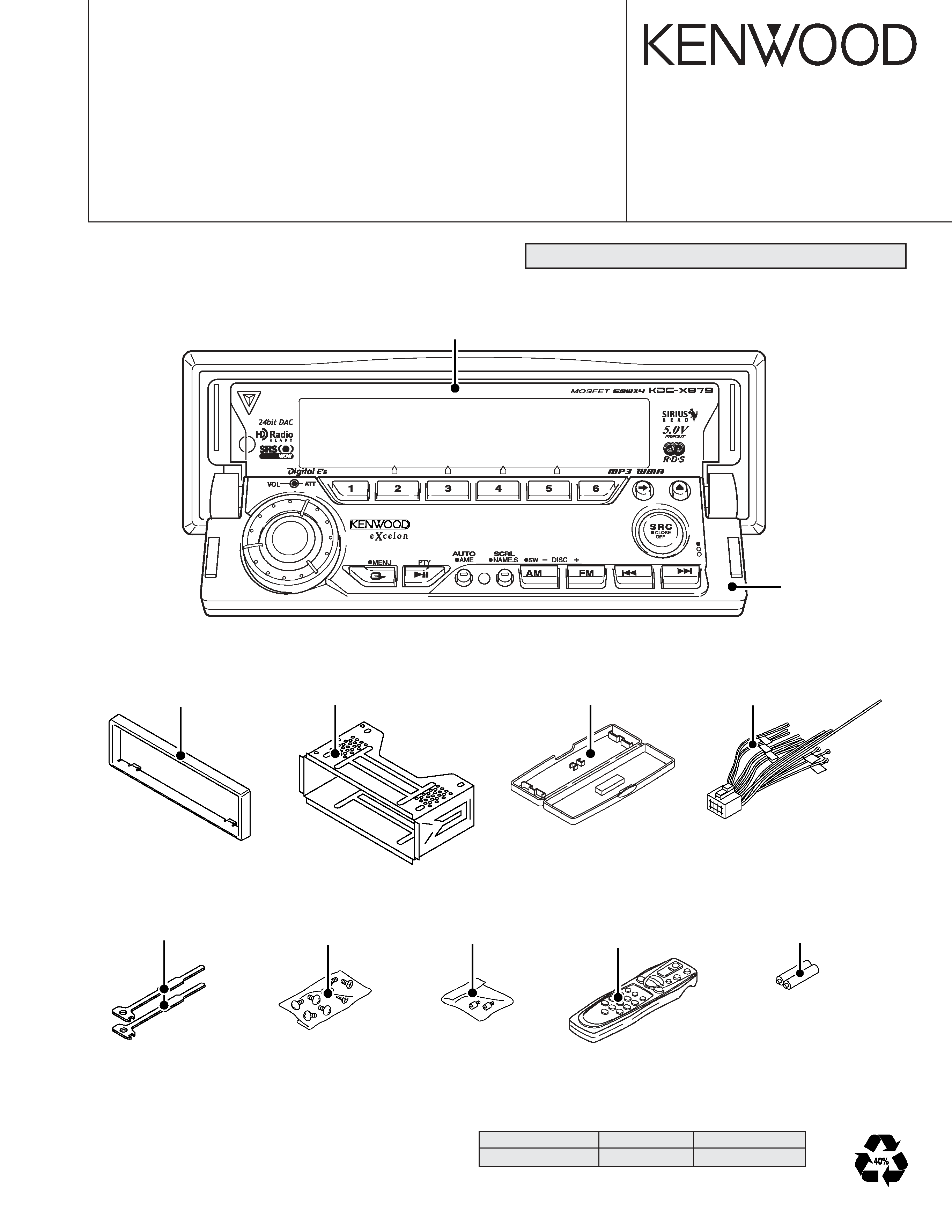
KDC-X879
5
Ref No.
Application / Functions
Operation / Condition / Compatibility
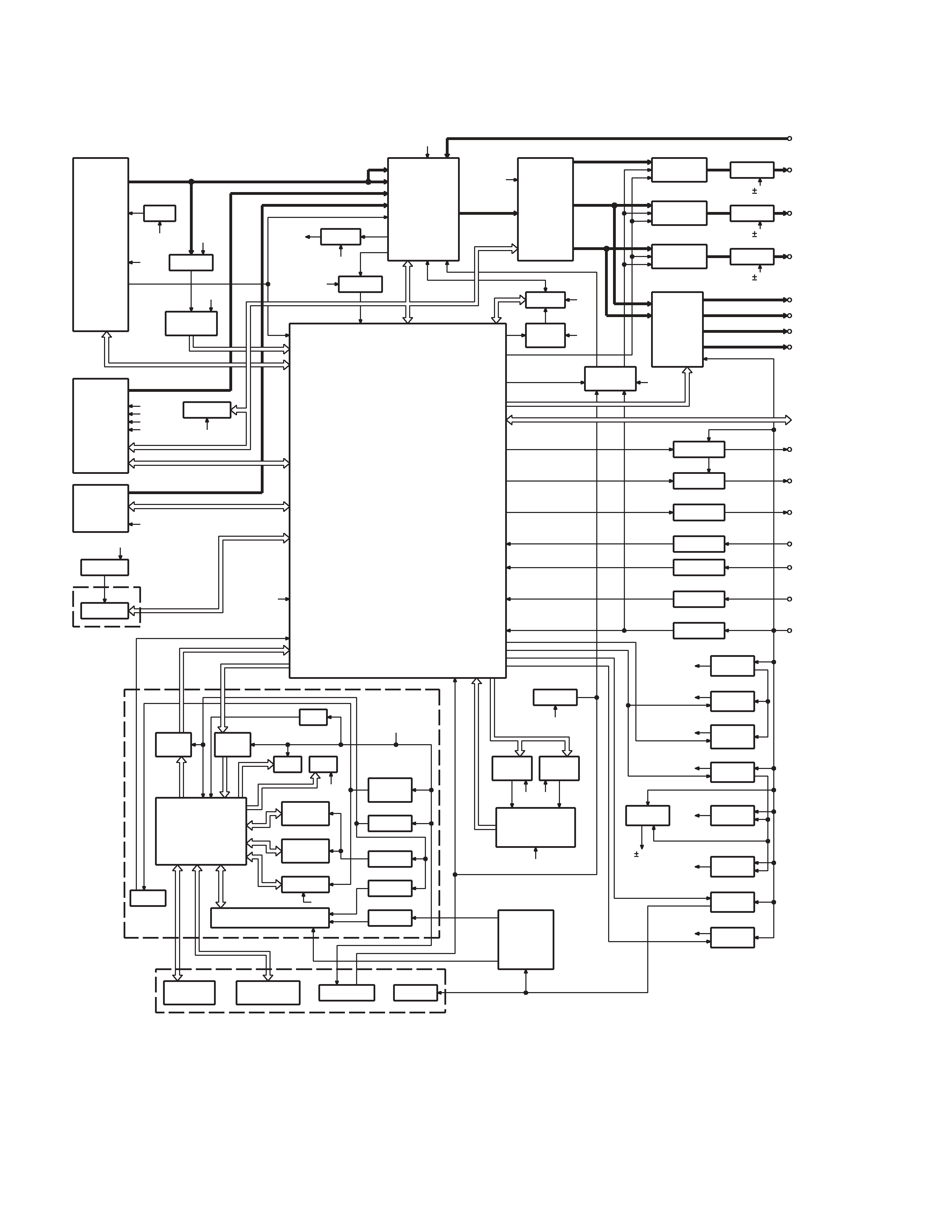
IC5
System IC
For System E's control
IC6
Audio control IC
For WOW/FOCUS control
IC7
Power supply IC
-9V AVR (For 4.5V Pre-out)
IC8
Reset IC
When BU5V line voltage is less than 3.5V, this IC output line is "L"
IC9
Muting logic IC
Control for MUTE, P-ANT & RESET muting
IC10
Buffer IC
For spectrum analyzer
IC11~13
OP AMP
For 4.5V Pre-out
IC14
RDS decoder
Decode for RDS signal
IC15,16
Motor driver
Control for Panel mechanism motor
IC18
P-CON IC
Power control IC
IC19
Power supply IC
Switching regulator IC for CD4.7V
IC20
Analog SW
Control for WOW/FOCUS IC (IC4)
Q1,2
BU 5V AVR
While BU is applied when BU5V regulator output is +5V
Q3,601
SW5V AVR
When Q601base level goes H, SW5V regulator output is +5V
Q4,5
SW14V AVR
When Q5 base level goes H, SW14V regulator output is +14V
Q6~8
Audio 8V AVR
When Q6 base level goes H, A8V regulator output is +8.3V
Q9,602
Servo +B AVR
When Q602 base level goes H, S+B regulator output is +7.5V
Q11~14
Illumination & DC/DC +B AVR
When Q11 base level goes H, AVR output is +9.2V
Q15,16
Audio 10.5V AVR
When Q16 base level goes H, AVR output is +10.5V
Q17~19
Pre Amp & -9V AVR
Q18,19 work as differential amplifier, Q17 wark as driver and -9.1V is supplied to
OP AMP for Pre-out
Q20~22
Pre Amp & +9V AVR
Q20,22 work as differential amplifier, Q21 wark as driver and +9.4V is supplied to
OP AMP for Pre-out
Q23,24
P-ANT SW
When Q23 base level goes H, P-ANT SW output is +14V
Q25
Buffer
EX amp control buffer
Q26
Small lamp det. SW
When Q26 base level goes H, Q26 turned ON
Q27
BU detector
When Q27 base level goes H, Q27 turned ON
Q29
ACC detector
When Q29 base level goes H, Q29 turned ON
Q30,31
Muting driver
When base level goes L, muting driver is turned ON
Q201
Buffer
Noise detect buffer amp
Q202
E-VOL muting SW
When Q202 base level goes H, muting SW is turned ON
Q203~208
Pre-out muting SW
When base level goes H, Pre-output is muted
Q210
AGC
For AGC for spectrum analyzer
Q303,304
AM +B SW
When Q303 base level goes H, AM +B is out to tuner unit
Q305
Buffer
Composite signal buffer for RDS
Q501
E2P 5V SW
When Q501 base level goes L, E2P 5V is out for E2PROM
Q502,503
Panel 5V SW
When Q503 base level goes H, Panel 5V is out
Q603
SW
When Q603 base level goes H, Q603 is turned ON
COMPONENTS DESCRIPTION