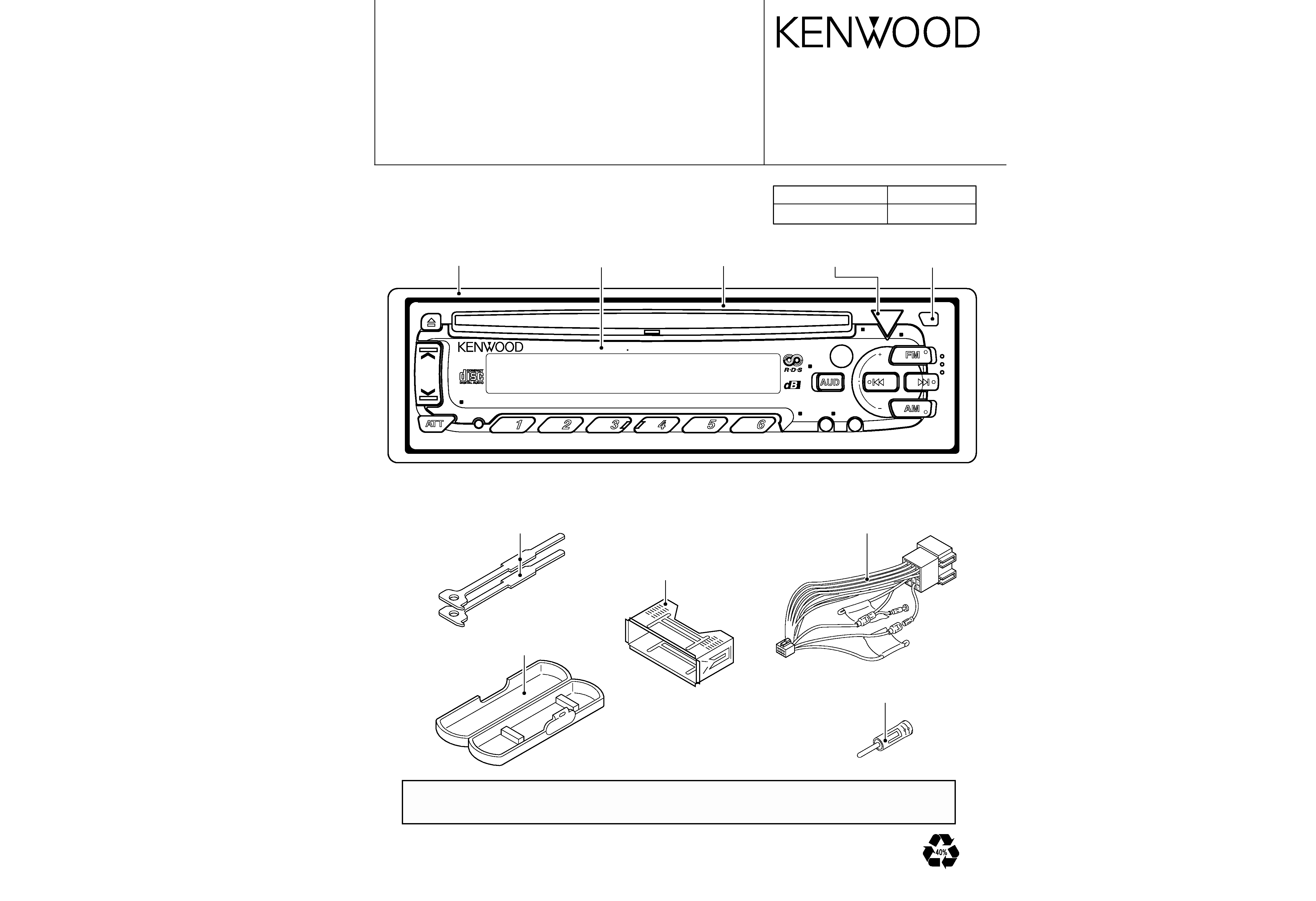
KDC-4080R/RV/RY/RYV
3
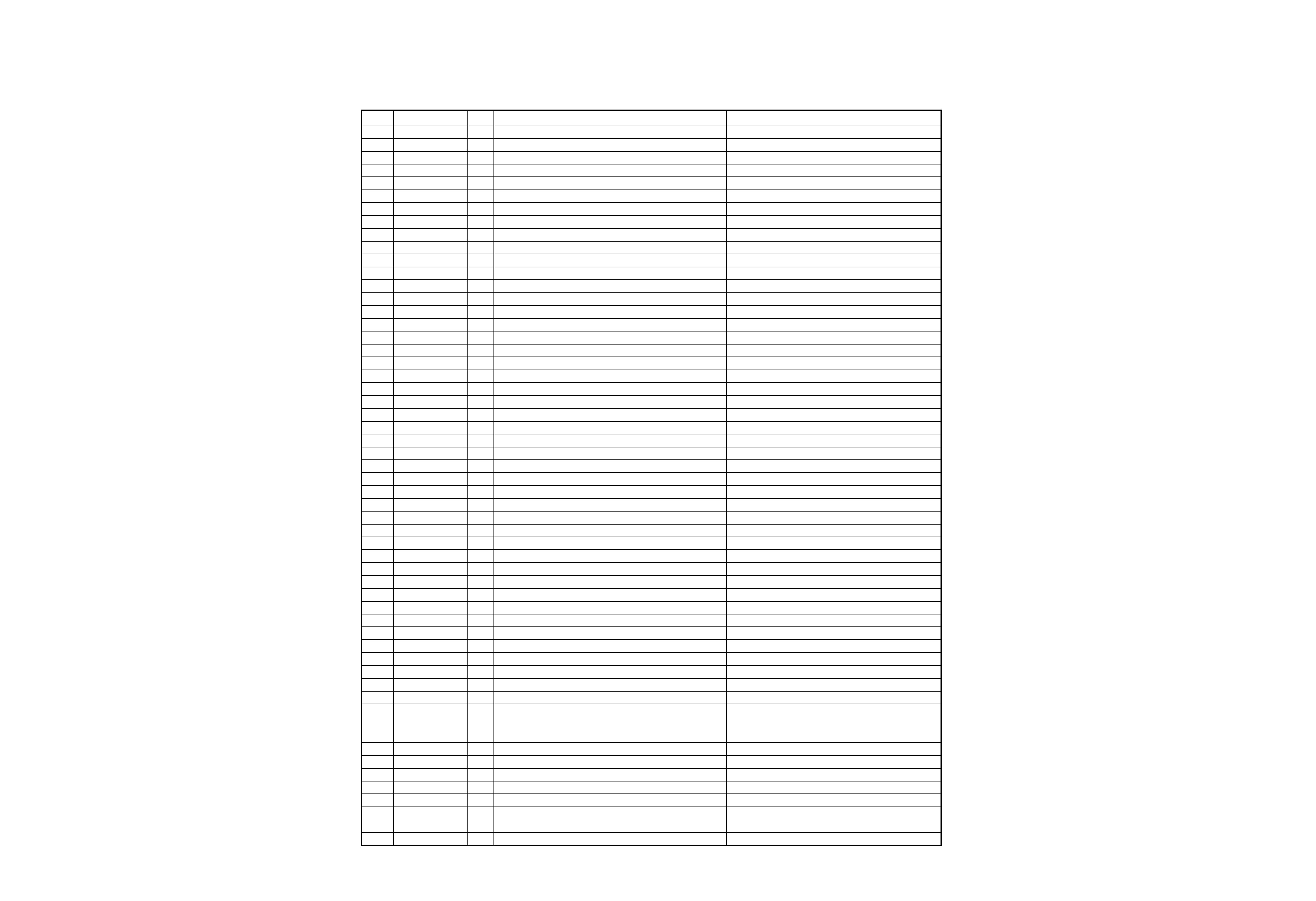
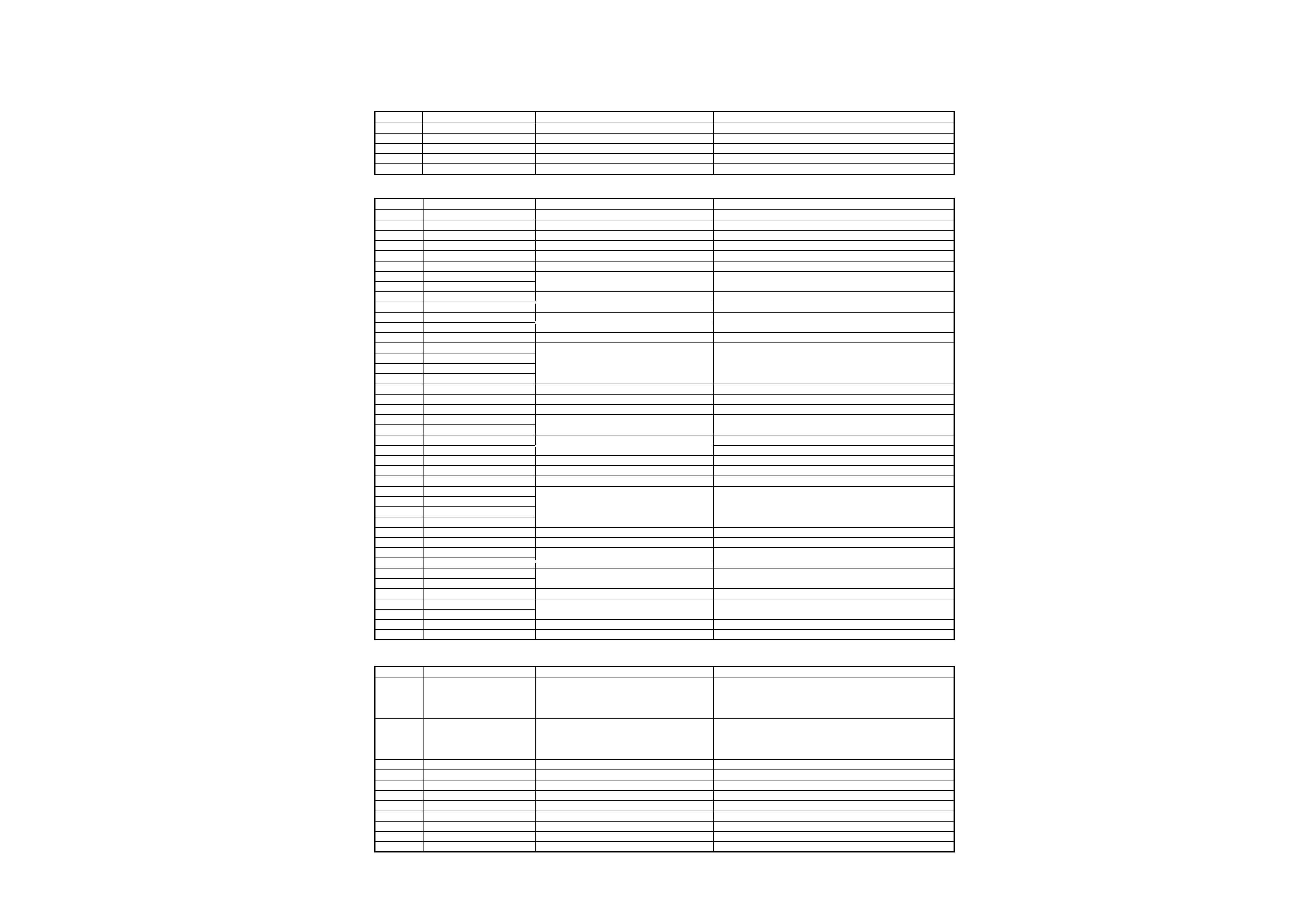
qELECTRIC UNIT(X25-84X2-7X)
Ref.No.
Component Name
Application/Function
Operation/Condition/Compatibility
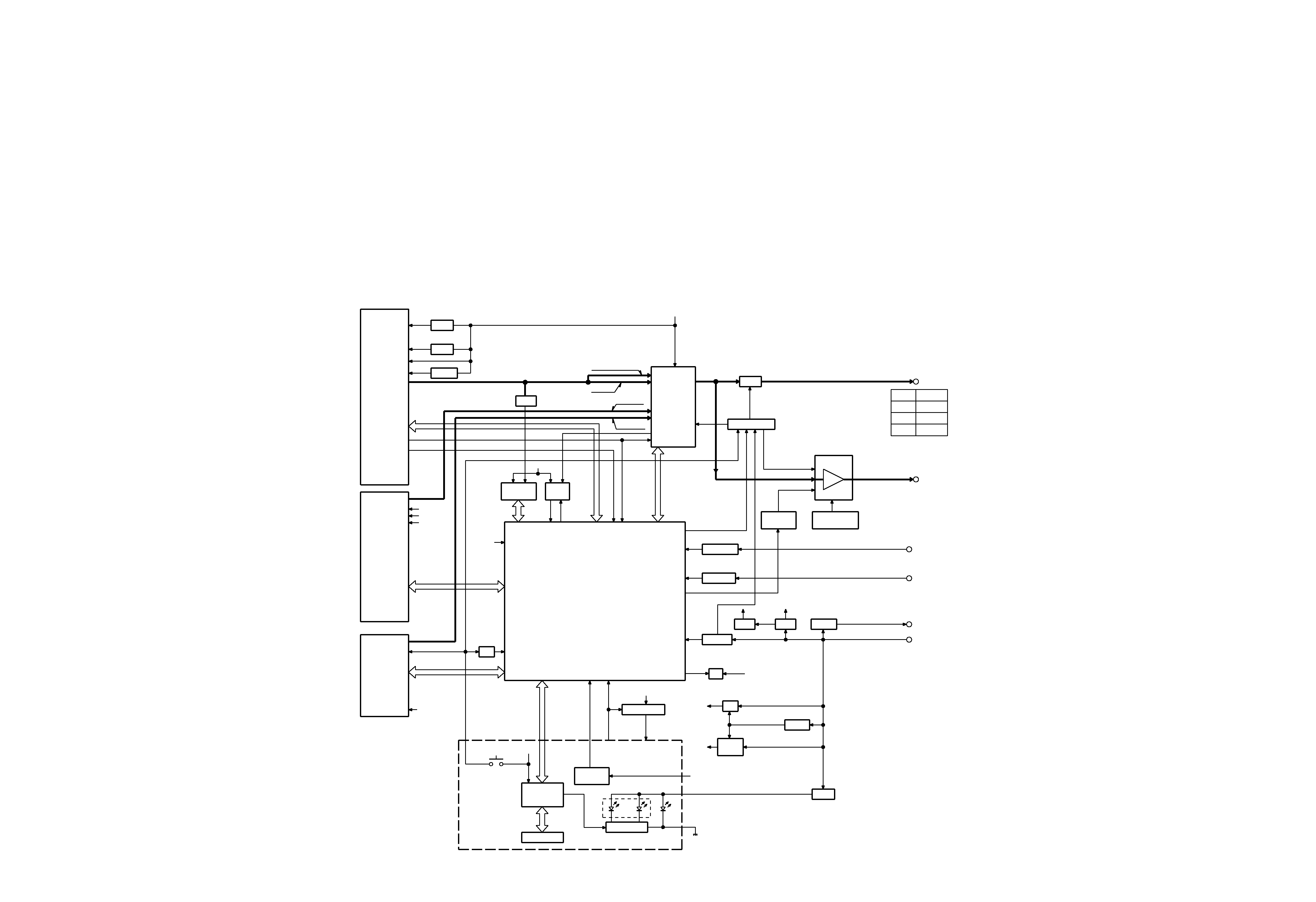
IC1
UPD780058GC107
System MI-COM.
IC2
TDA7400D
E-VOL. & N.C. MPX
IC3
PST9130NR
Reset IC
"Lo": Detection voltage below 3.0V
IC4
TDA7384A
Power IC
IC5
HD74HC27FP
Mute logic
3 input NOR gate x3
IC6
TDA7479D
RDS decoder
Q1
2SB1565F(E,F)
BU 5V AVR
Inverted darlington connection
Q2
2SC1740S
ON during BU applied
Q3
DTA124EKorUN2112
SW14V
Audio 8V AVR and Servo AVR ON/OFF control
Q4
DTC144EKorUN2213
Q3 is turned ON when Q4's base goes "Hi".
Q5
2SB1184
Audio 8V AVR
Q5 is turned ON when Q6's base goes "Hi".
Q6
2SC1740S
Inverted darlington connection
Q7
2SD2396F40
Servo AVR
ON when the base goes "Hi".
Q8
DTC144EKorUN2213
Illumination AVR
Q10 is turned ON when Q8's base goes "Hi".
Q9
DTA124EKorUN2112
Q10
2SB1184
Q11
2SC1740S
Q12
2SC1740S
BU detection(Momentary power down detection)
ON when the base goes "Hi" during BU applied.
Q13
2SC1740S
ACC detection
ON when the base goes "Hi" during ACC applied.
Q14
2SA1036K
SW 5V
ON when the base goes "Lo".
Q17
2SB1277(Q,R)
P-CON SW
Q17 is turned ON when Q20's base goes "Hi".
Q20
DTC114YKorUN2214
ON while power is on or CD loading/eject.
Q18
2SA1037K
P-CON protection
Protect Q17 by turning ON when P-CON output is grounded.
Q19
DTA124EKorUN2112
Prevents Q18 tuning ON during start-up after power ON.
Q50
DTC144EKorUN2213
RESET SW
System RESET is activated when the panel reset SW is pressed.
Q51
2SC2412Kor2SD601A
DSI SW
ON when the base goes "Hi".
Q150
DTC114YKorUN2214
SVR SW
POWER IC RESET is activated when the base goes "Hi".
Q151
DTC143TKorUN2216
Audio mute SW
Audio pre-outs are muted when the base goes "Hi".
Q152
DTC143TKorUN2216
Q153
DTC143TKorUN2216
Q154
DTC143TKorUN2216
Q155
DTA124EKorUN2112
Mute driver for Audio mute SW
ON when the base goes "Lo".
Q156
DTC144EKorUN2213
E-VOL. mute SW
E-VOL. is muted when the base goes "Hi".
Q200
2SB1277(Q,R)
FM+B SW
Q200 is turned ON when Q201's base goes "Hi".
Q201
DTC124EKorUN2212
ON during FM reception
Q202
2SB1277(Q,R)
AM+B SW
Q202 is turned ON when Q203's base goes "Hi".
Q203
DTC124EKorUN2212
ON during AM reception
Q204
2SC1740S
Tuner audio out buffer
Q205
DTC114TKorUN2215
AFC time constant SW
OFF during FM seek,ON during FM reception
Q206
DTA124EKorUN2112
Q205 is turned OFF when Q206's emitter goes "Lo".
Q207
2SA1037K
Panel detection SW
ON when the base goes "Lo" during the panel closed.
Q208
2SC1740S
Noise buffer
COMPONENT DESCRIPTION
qSWITCH UNIT(X13-96X2-7X)
Ref.No.
Component Name
Application/Function
Operation/Condition/Compatibility
IC1
LC75883E
LCD driver with key-matrix
IC2
RS-171
Remote control light sensor
Q1
DTA114EKorUN2111
key-matrix permission SW
Ready on key-matrix
Q2
2SD2114K
key illmination SW (Green)
ON when the base goes "Hi".
Q3
2SD2114K
key illmination SW (Red)
ON when the base goes "Hi".
qCD PLAYER UNIT(X32-4600/4700-00)
Ref.No.
Component Name
Application/Function
Operation/Condition/Compatibility
IC1
AN8806SB
RF amplifier
Generation of RF signal based on the signals from the APC
circuit and pickup, and generation of servo error(focusing
error and tracking error) signals. Detection of dropout, anti-
shock, track crossing and off-track conditions.
IC2
MN662770KA7
CD signal processor bult-in MI-COM.
Focusing,tracking,sled and spindle servo processing. Automatic
adjustment(focusing, tracking, gain, offset and balance) operations.
Digital signal processing(DSP, PLL, sub-codes, CIRC error
correction, audio data interpolaration) operations.
IC4
BA5917AFP
BTL driver
Focusing coil, tracking coil, spindle motor and sled motor driver
IC5
TA78L05F
5V AVR
IC6
NJM4565MD
Low pass filter
Q1
2SA1362(Y)
APC
LD power control
Q2
DTC124EUA
POWER SW
Power on during the source selected CD
Q3
2SA1362(Y)
A.8V SW
A8V line ON/OFF control
Q4
2SA1362(Y)
D.5V SW
D5V line ON/OFF control
Q5
DTC124EUA
MOTOR ON SW
Power on during CD roading or eject action
Q6
2SA1576A
TE LEVEL SW
OFF during CDR play