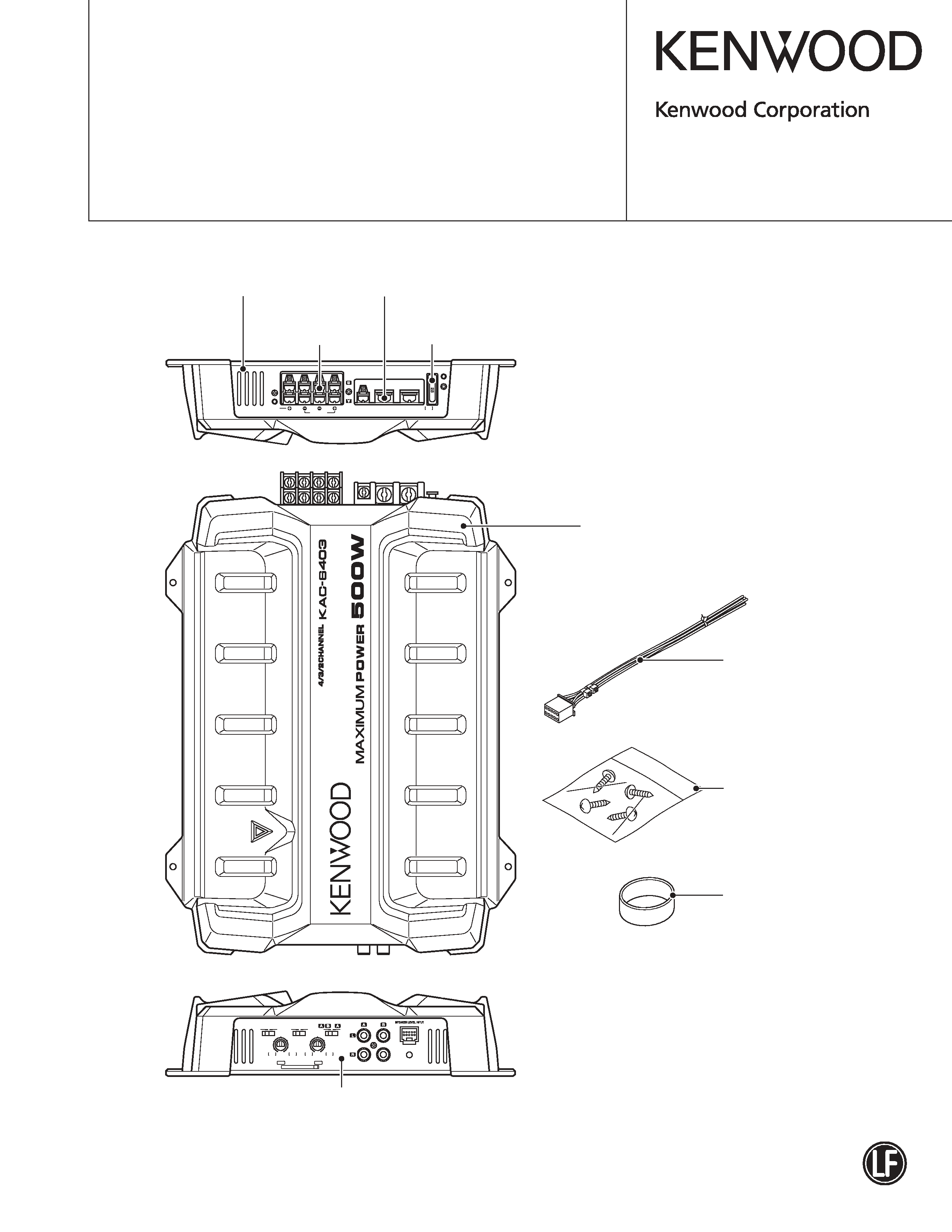
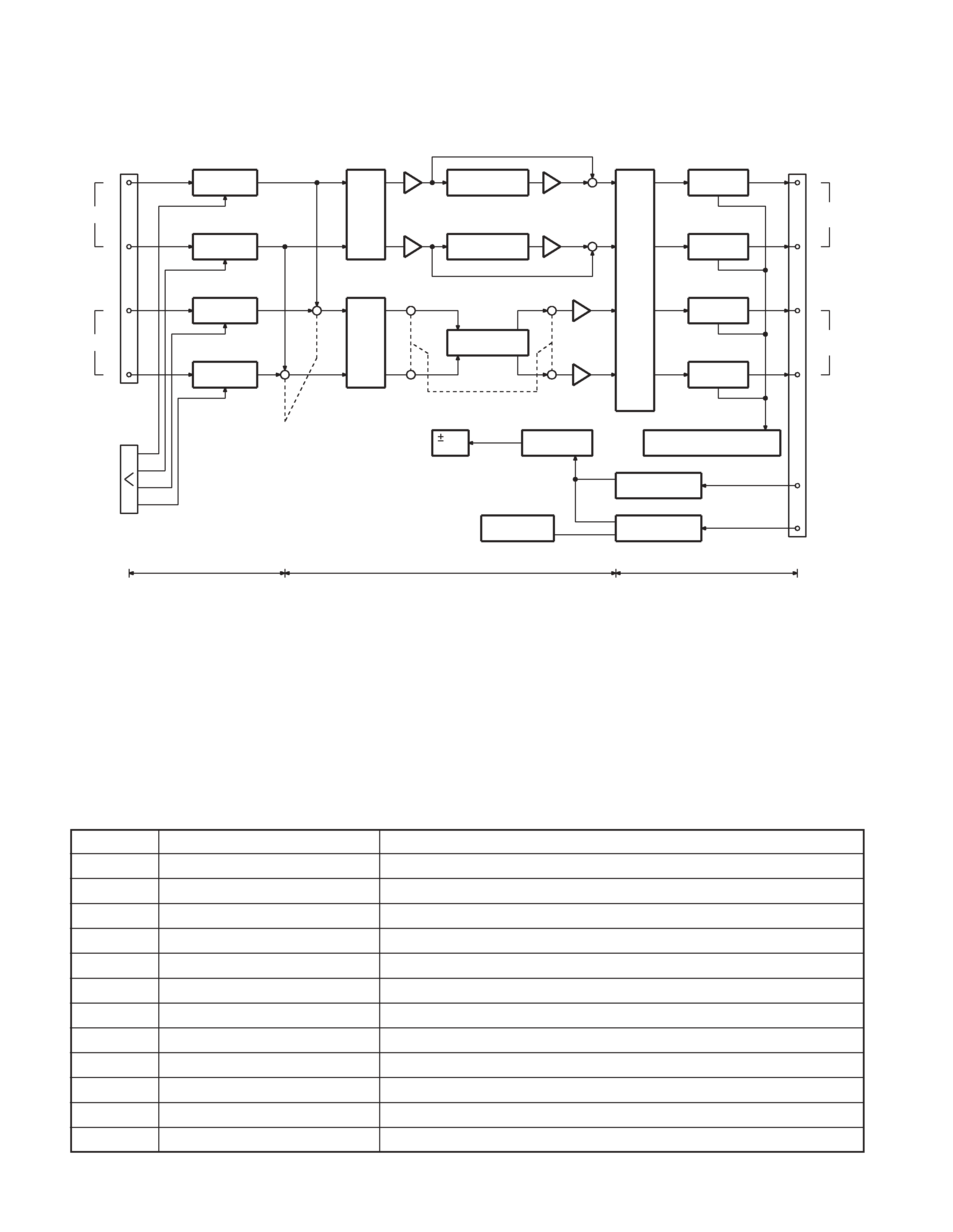
KENWOOD KAC-6403 Service Manual

Cover page of KENWOOD KAC-6403 Service Manual

Service Manual for KENWOOD KAC-6403, downloadable as a PDF file.

We also have owner's manual to this model.

Manual details

  • Immediate download after payment.
  • Delivered as a PDF file.
  • The manual has 14 pages
  • File size: 0.71 MB
  • Available language versions: English
  • Different language versions may vary sligthly in file size and page count.

We guarantee that...

  • our manuals are complete,
  • the manual includes circuit diagrams,
  • our manuals are checked with antivirus,
  • We'll issue refund if the manual is damaged, incomplete or unreadable (our refund policy)

Sample pages

Thumbnail of page 1Thumbnail of page 2Thumbnail of page 3Thumbnail of page 4
Thumbnail of page 5Thumbnail of page 6Thumbnail of page 7Thumbnail of page 8
Thumbnail of page 9
background image
© 2006-1 PRINTED IN JAPAN
B53-0378-00 (N) 540
POWER AMPLIFIER
KAC-6403
SERVICE MANUAL
Screw washer
(N09-4215-08)
Panel
(A64-3834-02)
Heat sink
(F01-3511-01)
Screw set
(N99-1587-05)
Accessory
(W01-1606-05)
A ch FILTER
B ch FILTER
INPUT SELECTOR
OFF
LPF
OFF
HPF
1
0.5
0.3
0.2
2
5
3
4
MIN
V
MAX
LINE IN
INPUT SENSITIVITY
1
0.5
0.3
0.2
2
5
3
4
MIN
MAX
Ach
Bch
POWER
IN
BRIDGED
LEFT
FUSE
BA TT
.
P .CON
GND
25A
RIGHT
SPEAKEROUT
PO
WER
AMPLIFIER
Fuse (25A)
(F52-0014-05)
Rear panel
(A84-0410-02)
Connecting cord assy
(E30-6144-05)
Screw washer
(N09-6393-08)
This product uses Lead Free solder.
EXPLODED VIEW is on page 5.
background image
KAC-6403
2
BLOCK DIAGRAM
+6dB
0dB
+29.5dB
AMPLIFIER
ISOLATION
IC2
AMPLIFIER
ISOLATION
IC2
GAIN
INPUT
VR1
CONT.
J1
R
L
LINE IN A
J2
SPEAKER
INPUT
HPF
80Hz 12dB/OCT
C151,153,R165,167
80Hz 12dB/OCT
HPF
C152,154,R166,168
MUTE
201,202
AMPLIFIER
POWER
119-126
Q103-114,
AMPLIFIER
POWER
J9
SPEAKER
R
OUT A
L
AVR
15V
Q3,4
CONVERTER
L2
DC/DC
OVER ROAD PROTECTION
DC DETECT &
Q115-118,215-218
CIRCUIT
P.CON
Q605
PROTECTION
THERMAL
TH1
P.CON
BATTERY
IC13
OVER VOLTAGE
PROTECTION
S2
S2
ISOLATION
AMPLIFIER
IC4
IC4
ISOLATION
AMPLIFIER
R
LINE IN B
L
INPUT
VR2
CONT.
GAIN
S1
S1
A-AB
Ach
Bch
Q101,102,
119-126
Q103-114,
IC7
+1
-3dB ATT
-3dB ATT
IC7
+1
IC9
+1
IC9
-1
80Hz 12dB/OCT
LPF+10dB
IC5
S3
S3
S3
S3
IC6
-3dB ATT
+1
-3dB ATT
-1
IC5
AMPLIFIER
POWER
R
OUT B
SPEAKER
AMPLIFIER
219-226
Q203-214,
POWER
L
219-226
Q203-214,
AUDIO UNIT (X09-8542-70)
COMPONENTS DESCRIPTION
AUDIO UNIT (X09-8542-70)
Ref. No
Application / Function
Operation / Condition / Compatibility
IC1
Buffer AMP
Amplifies 6dB by decreasing impedance.
IC2
Isolation AMP
Decreases common mode noise.
IC3
Buffer AMP
Amplifies 6dB by decreasing impedance.
IC4
Isolation AMP
Decreases common mode noise.
IC5
LPF
B-Rch side is phase inverter.
IC6
-3dB ATT
B-Lch side is buffer amplifier.
IC7
Buffer AMP
Decreases impedance.
IC9
Phase inverter
A-Lch side is buffer amplifier.
IC13
DC/DC converter
Oscillates and controls DC/DC converter.
Q3,4
Constant voltage power supply
Controls
±15V constant voltage.
Q5,6
DC/DC converter
Switching FET.
Q7~10
DC/DC converter
Drives Q5's and Q6's gates.
background image
KAC-6403
3
Ref. No
Application / Function
Operation / Condition / Compatibility
Q11,12
DC/DC converter
Turns on or off IC13 output.
Q101,102
Input mute
Absorbs shook noise when power turns on or off.
Q103~106
Power AMP
1st deferential amplifier.
Q107~110
Power AMP
2nd deferential amplifier.
Q111,112
Power AMP
Current mirror load for 2nd deferential amplifier.
Q113,114
Power AMP
Compensates bias temperature in power amplifier.
Q115~118
Power AMP
Detects over-current.
Q119~122
Power AMP
Darlington driver.
Q123~126
Power AMP
Darlington output.
Q131,132
ATT signal control
Controls signal in attenuator.
Q201,202
Input mute
Absorbs shook noise when power turns on or off.
Q203~206
Power AMP
1st deferential amplifier.
Q207~210
Power AMP
2nd deferential amplifier.
Q211,212
Power AMP
Current mirror load for 2nd deferential amplifier.
Q213,214
Power AMP
Compensates bias temperature in power amplifier.
Q215~218
Power AMP
Detects over-current.
Q219~222
Power AMP
Darlington driver.
Q223~226
Power AMP
Darlington output.
Q231,232
ATT signal control
Controls signal in attenuator.
Q601
B-class stage mute
Generates mute signal. ON: Normal
Q602
Mute
Generates mute signal. OFF: Normal
Q603
Input mute
Generates mute signal. OFF: Normal
Q604
Power ON/OFF
Controls primary power supply. ON: Normal
Q605
Power ON/OFF
Controls power.
Q606
Power ON/OFF
Protects from over-voltage. Stops when primary power supply input voltage is below 16V.
Q610
Over-current DET
Operates when Q610 detects over-current, and DC/DC converter turns off.
Q611,612
DC output voltage DET
Operates when DC output voltage is in power amplifier.
Q613,614
DC output voltage DET
Latch circuit for DC to be detected.
Q615,616
B-class stage mute
Operates to turn off input of power amplifier.
Q617,618
B-class stage mute
Drives Q615 and Q616. ON: Normal
D1
Wrong connection protection
Cuts fuse off when connector is connected wrongly.
D2,3
AVR reference voltage
Controls Q3 and Q4 with zener voltage.
D4,5
Secondary power supply rectifier
D6~10
Switching
Prevents reverse flow.
D32~37
Static electricity protection
Prevents OP-AMP to be broken by static electricity.
D101,102
Temperature compensator
Stabilizes current between base and emitter of 2nd deferential transistors.
D103,104
Current mirror
Current mirror load for 2nd deferential amplifier.
D105,106
B-class stage mute
Prevents reverse flow.
D107~111
Over-current DET
Prevents reverse flow.
D201,202
Temperature compensator
Stabilizes current between base and emitter of 2nd deferential transistors.
COMPONENTS DESCRIPTION
background image
KAC-6403
4
Ref. No
Application / Function
Operation / Condition / Compatibility
D203,204
Current mirror
Current mirror load for 2nd deferential amplifier.
D205,206
B-class stage mute
Prevents reverse flow.
D207~211
Over-current DET
Prevents reverse flow.
D601
LED control
Controls D610's power indicator.
D602,603
Mute control
Prevents reverse flow.
D604
Mute AVR
10V
D605
Power control
Prevents reverse flow.
D606
Over-current DET
Level shift for primary power supply.
D607
Power control
Level shift
D608
Mute control
Being controlled by Q602.
D610
LED
Being controlled by Q602.
D613,614
DC protection
Operates when DC is output.
D616
POP mute
COMPONENTS DESCRIPTION
No.
Item
Alignment Point
Method
Align for
Note
Fig.
Connect a DC voltmeter between
VR5 (A-Lch)
the following emitter resistors.
PC BOARD
1
IDEL CURRENT
VR6 (A-Rch)
R253 (A-Lch)
2.5mV
Over 5 minutes
on page 6
VR7 (B-Lch)
R254 (A-Rch)
aging is required.
and 7.
VR8 (B-Rch)
R453 (B-Lch)
R454 (B-Rch)
ADJUSTMENT
background image
KAC-6403
6
A
B
C
D
E
1
2
3
4
5
6
7
PC BOARD (FOIL SIDE VIEW)
R223
R225
R423
R425
R608
R609
R619
R668
R629
R666
R669
C15
C609
C610
C617
R10
R11
R16
R17
R19
R23
R26
R27
R606
R613
R614
R635
R636
R661
R662
R663
R664
R670
C14
C217
C219
C221
C222
C417
C419
C421
C607
C
R12
R13
R14
R15
R18
R20
R21
R22
R24
R25
R28
R209
R213
R219
R221
R229
AL
R231
R233
R235
R237
R238
R239
R241
R242
R243
R
R249
R251
R252
R413
R419
R421
R429
R431
R433
R435
R437
R439
R441
R443
R449
R451
R604
R605
R607
R610
R611
R612
R617
R620
R621
R622
R623
R632
R633
R634
R637
R665
R667
R671
TH1
TP44
W506
W533
W559
W535
W534
W537
W542
W539
W538
W536
R269
W546
W545
W543
W544
W541
W540
W557
W558
W592
W578
W579
9
16
8
1
BE
B
E
BE BE
BE
BE
B
E
B
E
BE
BE
BE
B
EB
E
BE
BE
B
E
BE
B
E
B
E
BE
BE
EB
BE
B
E
B
E
B
E
B
E
B
E
B
E
B
E
ID
B
BL
IDL+
AL
IDL+
AL
IDL-
AR
IDL+
2200uF
2200uF
W191
C1
W192
C6
C7
C606
R261
C18
R602
R618
C8
C9
C10
C17
C223
C224
C261
C423
C424
C601
C602
C603
3
4
5
6
79
1
0
11
8
1
2
C608
L2
C12
C13
C16
C211
C411
R7
R8
R9
R245
R247
R248
R253
R255
R256
R257
R258
R445
R447
R453
R455
R457
R458
R603
R615
R616
W203
W202
W26
W85
W88
W86
W87
W80
W78
W79
W104
W128
W124
W101
W103
W105
W118
W133
W83
W120
W112
W106
W107
W108
W126
W102
W130
W135
W93
W119
W125
W129
W134
W94
W163
W902
W167
W170
W169
W168
W159
W157
W160
W162
W161
W156
W155
W153
W152
W151
W141
W154
W158
W166
W165
W92
W84
W91
W89
W90
W131
W121
W116
W113
W146
W137
W117
W123
W96
W109
W110
W111
W145
W122
W144
W143
W149
W148
W147
W175
W100
W138
W115
W114
W127
W132
W98
W97
W136
W139
W99
BL
W196
W198
W140
W189
W190
W188
W187
W176
W182
W177
W180
W179
W181
W183
W184
W185
W172
W150
W164
W186
W178
W142
W194
W195
L3
W201
E
B
E
B
E
B
B
E
E
B
E
B
EB
BE
G
SD
G
SD
E
B
B
EB
E
E
B
EB
Q610
Q7
Q8
D8
D604
D614
D616
Q9
Q10
Q602
Q605
Q606
Q611
Q612
Q613
D6
D7
D9
D101
D103
D105
D107
D109
D110
D111
D201
D203
D207
D
D601
D602
D603
D605
D606
D607
D613
Q11
Q12
Q
Q
Q601
Q603
Q614
Q615
Q616
Q617
Q618
Q
Q131
D608
D4
Q119
Q123
Q219
Q223
D5
Q121
Q122
Q125
Q126
Q604
J9
P1
Q5
Q6
Q107
Q109
Q111
Q113
Q115
Q117
Q118
Q207
Q209
Q211
Q213
Q215
Q217
VR5
VR7
D1
IC13
AUDIO UNIT
X09-8542-70 (J76-0189-01)
DC voltmeter
B-Lch 2.5mV
DC voltmeter
A-Lch
2.5mV

Reviews

There are no reviews of this manual yet.