Batteries(R6/AA) ...(2)
Audio video cord (Red, White, Yellow) ...(1)
(E30-2990-08)
Remote control unit ...(1)
(A70-1570-08)
Coaxial cable ...(1)
(E30-7235-08)
DV-705/DVF-R5070-S
2
ACCESSORIES / CAUTIONS
Accessories
Cautions
Caution on condensation
Before transporting or moving this unit, carry out the
following operations.
1. Set the POWER ON/OFF switch to the ON
without loading a disc.
2. Wait a few seconds and verify that the display
shown appears.
3. Set the POWER ON/OFF switch to OFF.
Note related to transportation and movement
Condensation(of dew) may occur inside the unit when there is agreat
difference in temperature between this unit andthe outside. Thisunit
may not function properly if condensation occurs. In this case, leave
the unit for a few hours and restart the operation after the condensa-
tion has dried up.
Be specially cautious against condensation in the following circum-
stances:
When this unit is carried from one place to another across a large
difference in temperature, when the humidity in the room where
this unit is installed increases, etc.
"DTS" and "DTS Digital Out" are trade-
marks of Digital Theater Systems, Inc.
Manufactured under license from Dolby Laboratories.
"Dolby" and the double-D symbol are trademarks of Dolby
Laboratories.
The marking of products using lasers
(For countries other than U.S.A. and U.S.-Military)
Inside this laser product, a laser diode classified as Class 2 laser radia-
tion is contained as alerted by the internal caution label shown above. Do
not stare into beam or view directly with optical instruments.
Location: DVD laser pick-up unit cover inside this product
CAUTION
VISIBLE AND INVISIBLE LASER RADIATION
WHEN OPEN. DO NOT STARE INTO THE BEAM OR
VIEW DIRECTLY WITH OPTICAL INSTRUMENTS.
DO NOT PRESSON THIS SURFACE
The marking this product has been classified as Class 1. It
means that there is no danger of hazardous radiation outside
the product.
Location: Back panel
CLASS 1
LASER PRODUCT
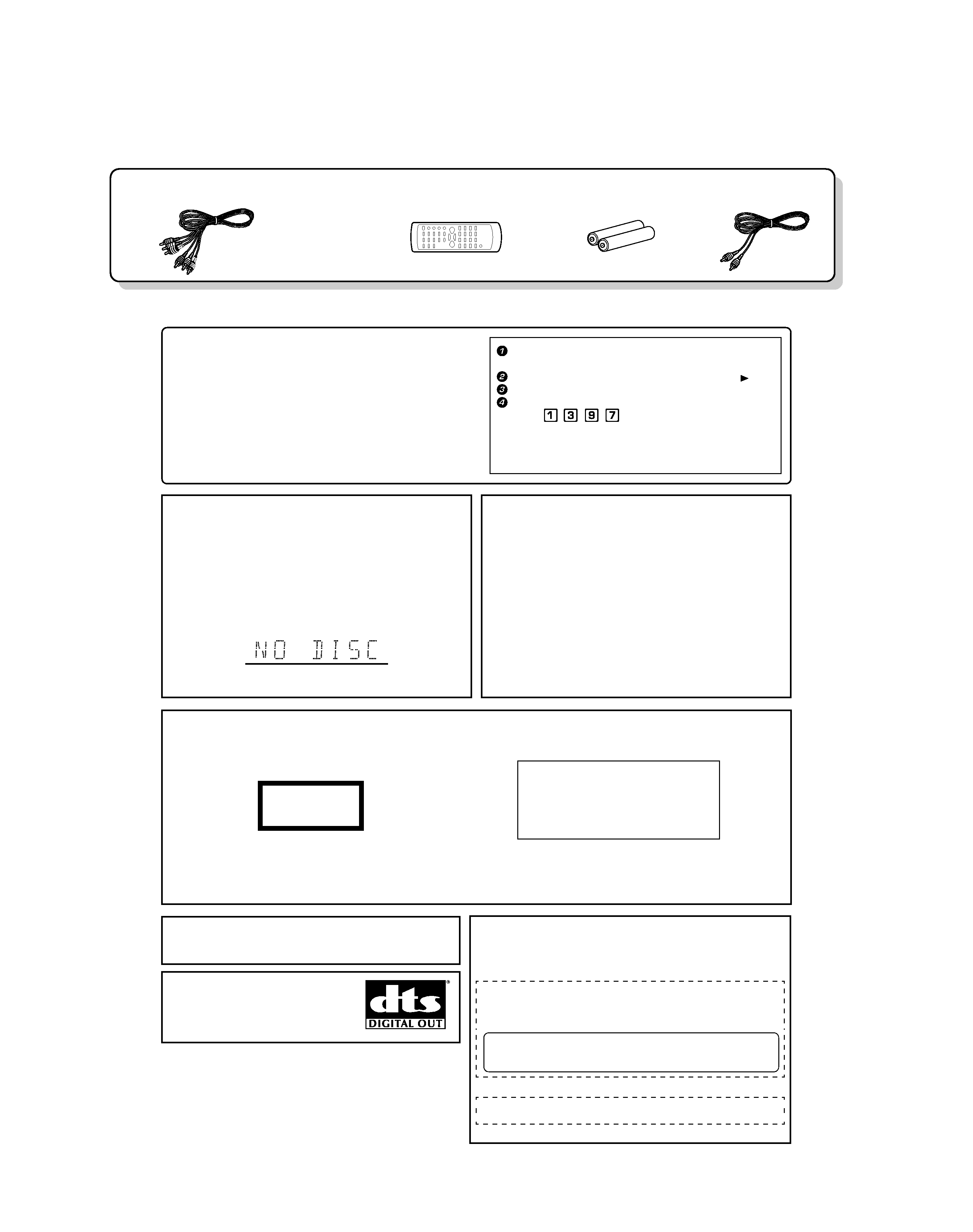
Operation to reset
During stop mode, press the MENU key on the remote to
enter "Control Panel" menu.
Select the "System" icon, then press the Cursor right ( ) key.
Select "Restore Setup Info".
Press the numeric keys as shown below.
Press
,
,
,
, then press the ENTER key.
When resetting is done according to this method, all settings,
including the settings for password and parental level, will be
reset to the factory defaults.
The microprocessor may fall into malfunction (impos-
sibility to operate erroneous display, etc.) when the
power cord is unplugged while power is ON or due to
an external factor.
In this case, switch off the power, wait for several sec-
onds, and then switch the power on again.
Return to the factory defaults by resetting the micropro-
cessor is done as shown as follows.
CAUTION:
Use of controls or adjustments or performance of procedures other than
those specified herein may result in hazardous radiation exposure.
In compliance with Federal Regulations, the following are reproductions
of labels on, or inside the product relating to laser product safety.
KENWOOD CORPORATION
2967-3, ISHIKAWA-CHO,
HACHIOJI-SHI,
TOKYO, JAPAN
KENWOOD CORP. CERTIFIESTHIS EQUIPMENT
CONFORMS TO DHHS REGULATIONS NO. 21 CFR
1040.10, CHAPTER1, SUBCHAPTERJ.
Location: Back Panel
CAUTION-
LASER RADIATION WHEN OPEN.
DO NOT STARE INTO BEAM.
Location: Laser Pick-up Unit Cover inside this product