3
DS-401TE
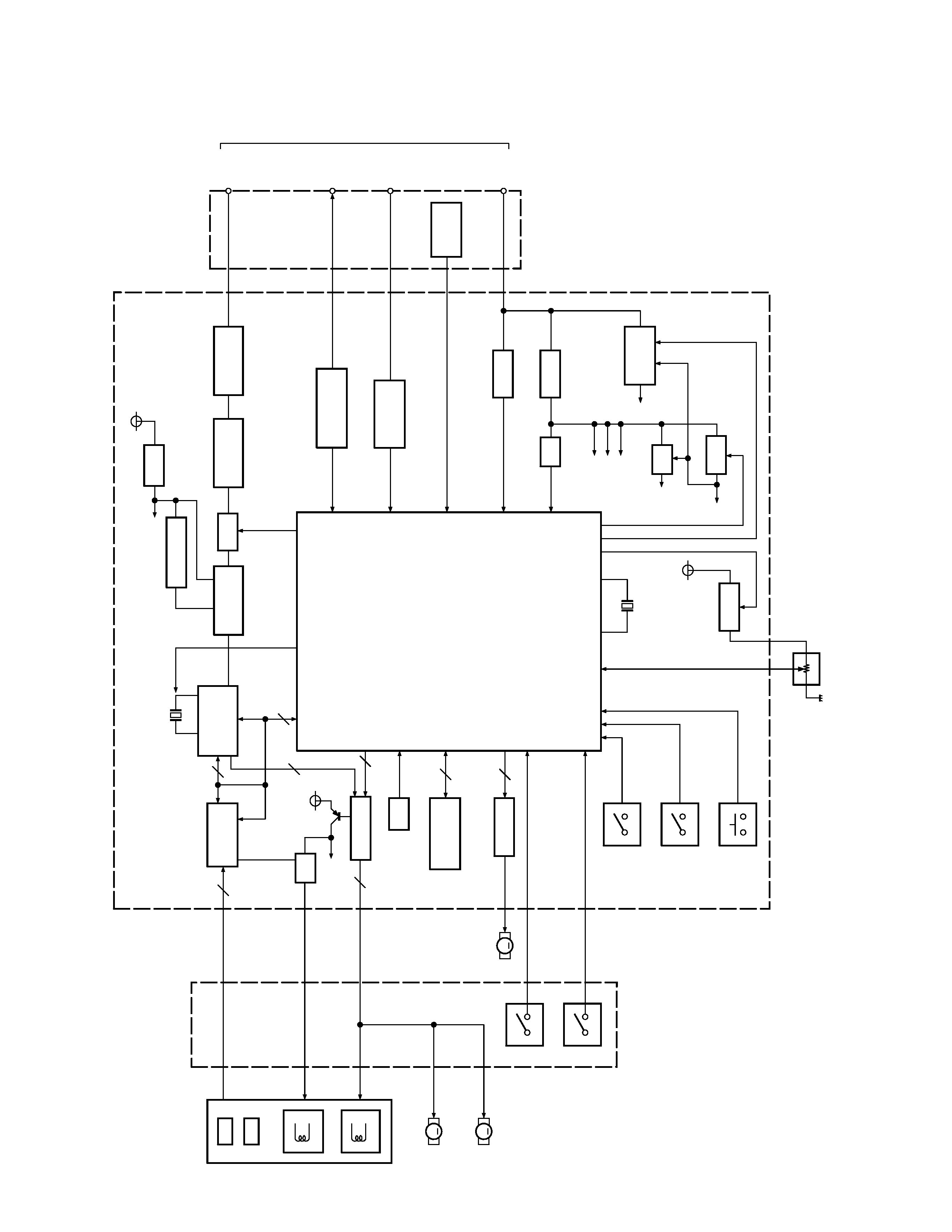
IC1
IC2
IC3
IC4
IC5
IC6
IC7
IC8
IC9
IC10
IC11
IC12
IC13
IC14
Q1
Q2
Q3
Q4, 5
Q6
Q7
Q8
Q9
Q10
Q11
Q12, 13
Q14
Q15, 16
Q17
Q20, 21
Q22
RF amplifier,error amplifier
Digital servo data processor
3-terminal regulator
D/A converter output active filter
Isolation amplifier
Isolation amplifier
Analog switch
Memory IC
System microcomputer
Reset IC
Motor drive
Motor drive
3-terminal regulator
IE-BUS driver/receiver
Laser control
Clock on/off
Audio mute driver
Audio mute
LSP power switch
P-ON switch
Optical system 5V power supply
Servo 5V drive
Servo 5V switch
BU power supply detection switch
AVR 8V drive
AVR 8V/7V selector switch
AVR 8V switch
SYS ON switch
Fo/Tr hold when scratches detected
Scratch detection switch
RF amplifier, focus tracking error amplifier, APC circuit, reference
amplifier, mirror circuit, DEFECT circuit, RFOK circuit, EFM comparator,
vibration detection circuit
Digital servo data processing circuit, 8 fs oversampling filter, D/A converter,
digital loop filter
D/A converter, active filter 5V power supply
Differential amplifer
Unbalanced/balance conversion - left channel
Unbalanced/balance conversion - right channel
CD deck initial UP/DOWN position
Focus tracking actuator, thread motor, spindle motor drive
CD deck elevator motor drive
Servo 5V power supply
Communications between head units and the CD changer
Laser current control through voltage output from IC1 LD terminal
Clock off when "H" output from IC9 XOFF terminal
Mute on when "L" output from IC9 AMUTE
Mute on when "L" output from IC9 AMUTE
On when IC9 LPSCO is "L" during the power turned on and CD desk operating
Supplied from AVR 8V to P.UP, IC1 and IC2 AVDD
Turns on/off when power turned on
7V when "H" (normal play mode), 8V when "L" (mechanism operation
Lo-Ej, ELV)
Turns on/off when power turned on
Conducts slave operation upon receiving SYS ACC from head unit
Focus error, traking error upon scratch detection
Reference hold of signal
Ref. No.
Use and Function
Operation and Condition
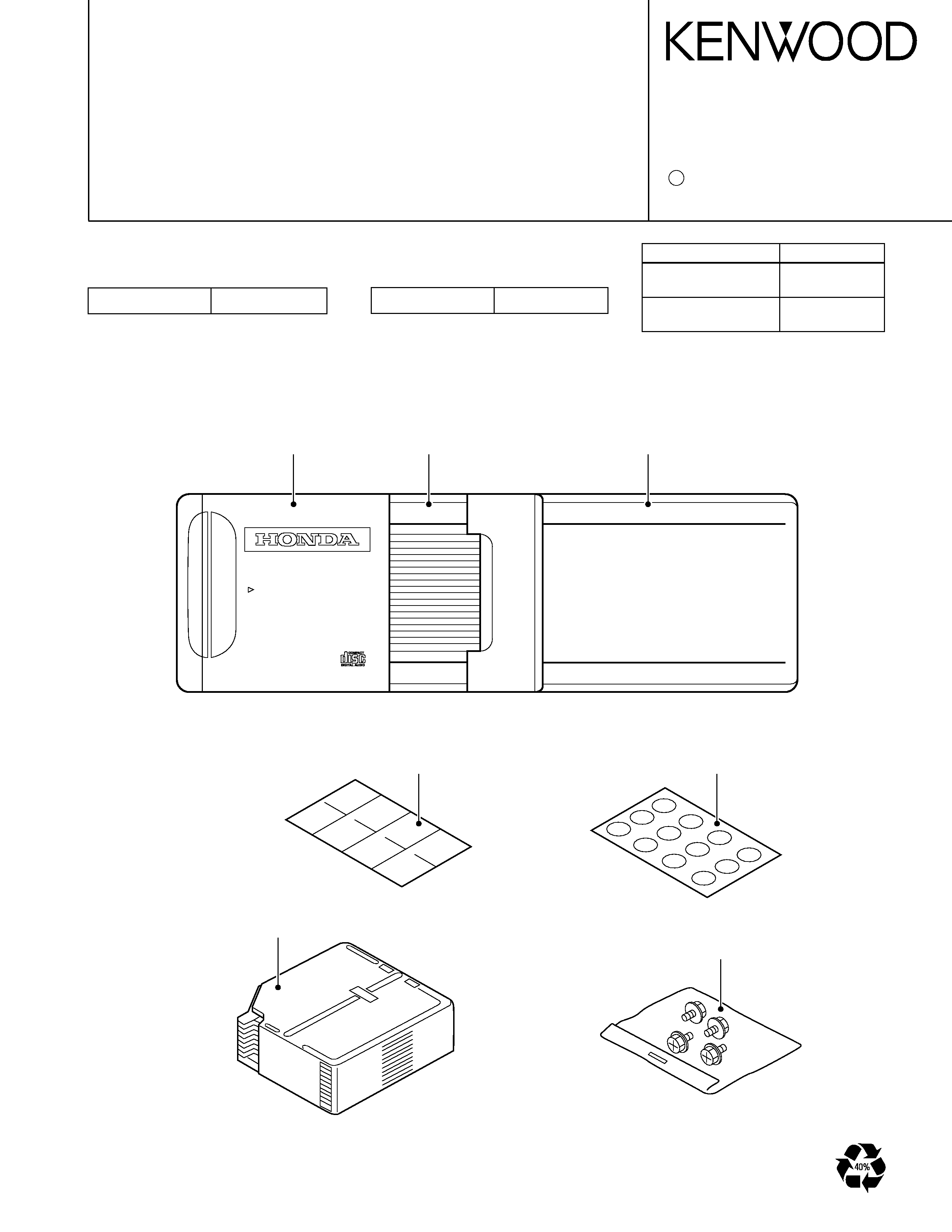
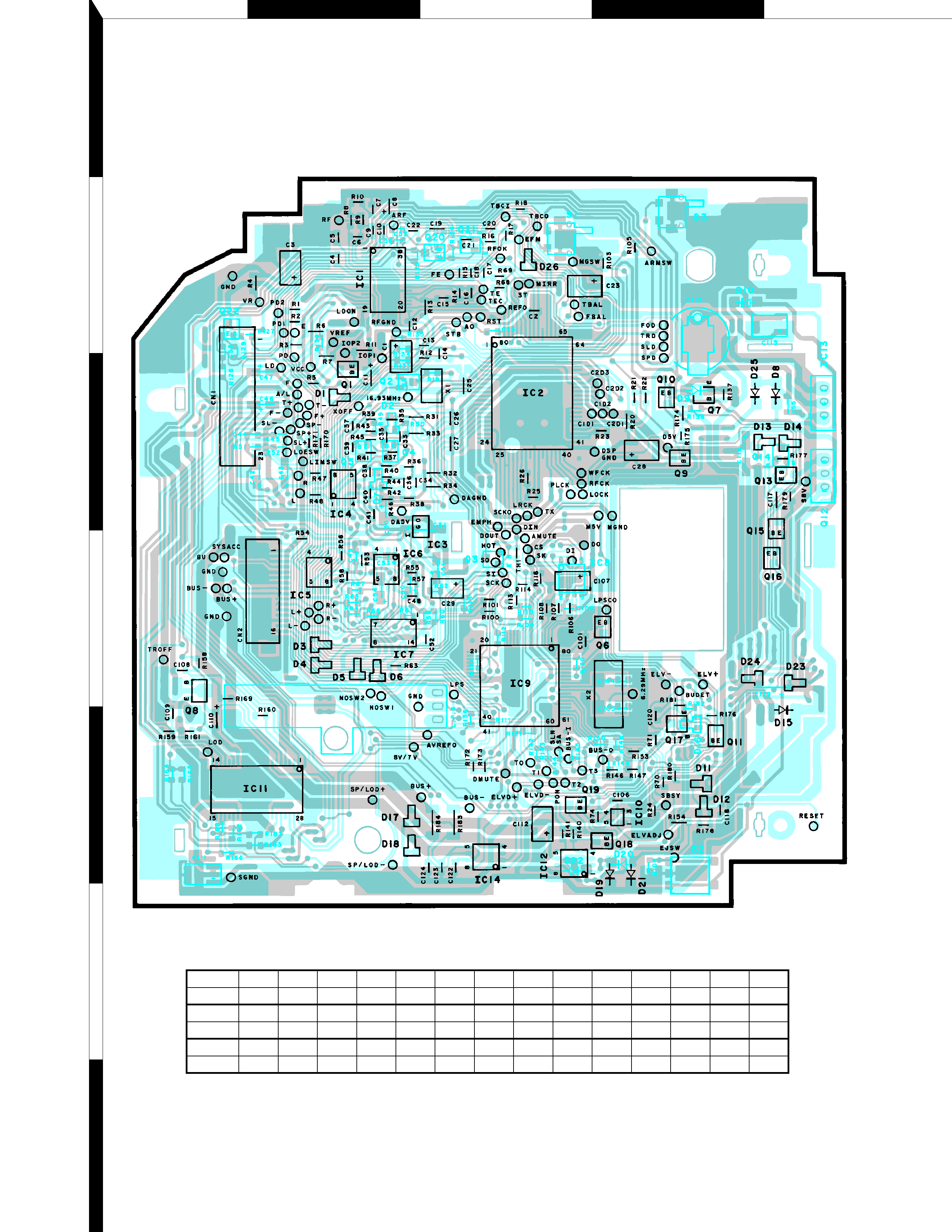
CD PLAYER UNIT (X32-4380-00)
COMPONENTS DESCRIPTION