3
Unpack the unit carefully and make sure that all accessories are put aside so they will not be lost.
Examine the unit for any possibility of shipping damage. If your unit is damaged or fails to operate, notify your dealer immediately. If your unit was shipped
to you directly, notify the shipping company without delay. Only the consignee (the person or company receiving the unit) can file a claim against the carrier
for shipping damage.
We recommend that you retain the original carton and packing materials for use should you transport or ship the unit in the future.
Keep this manual handy for future reference.
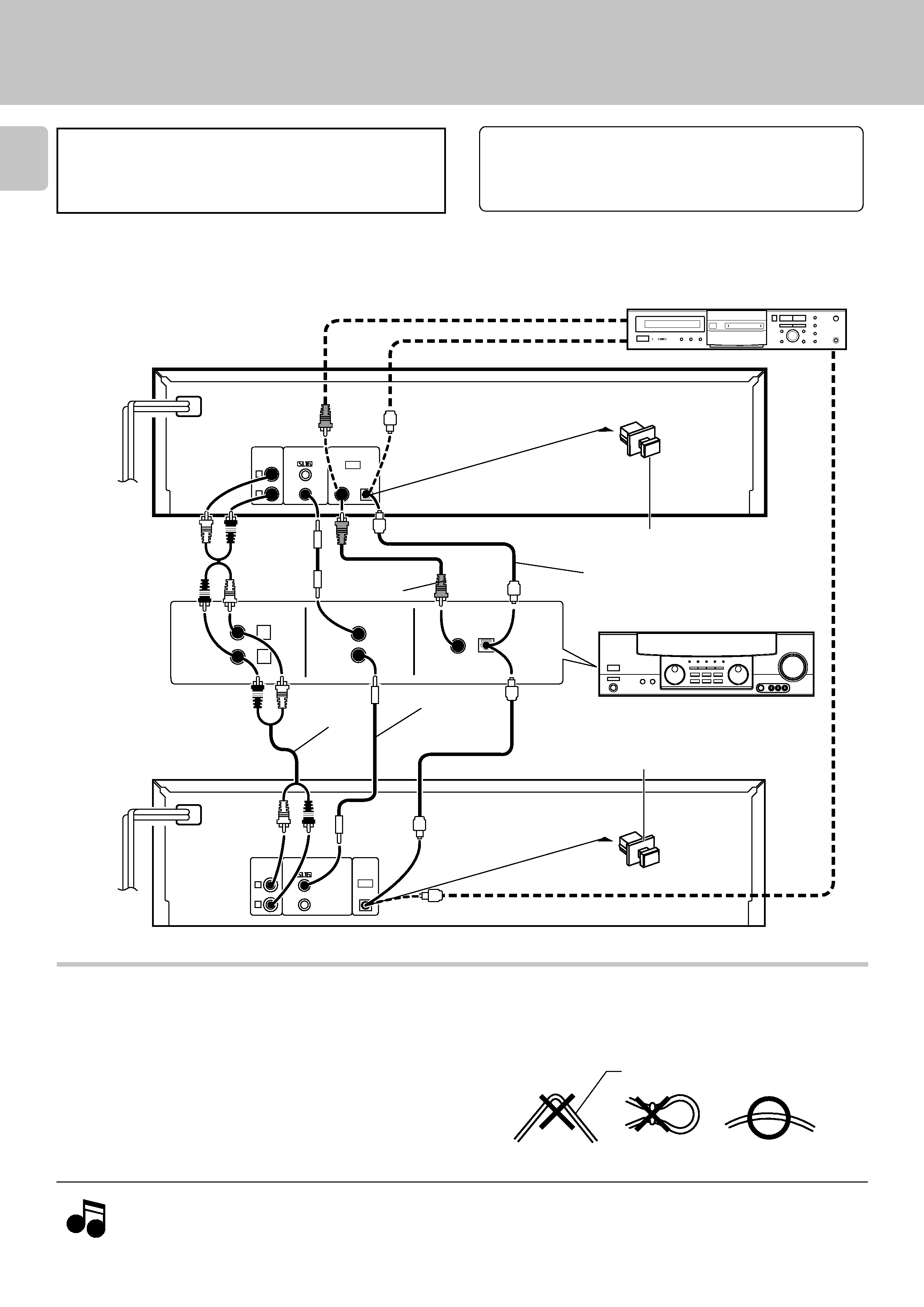
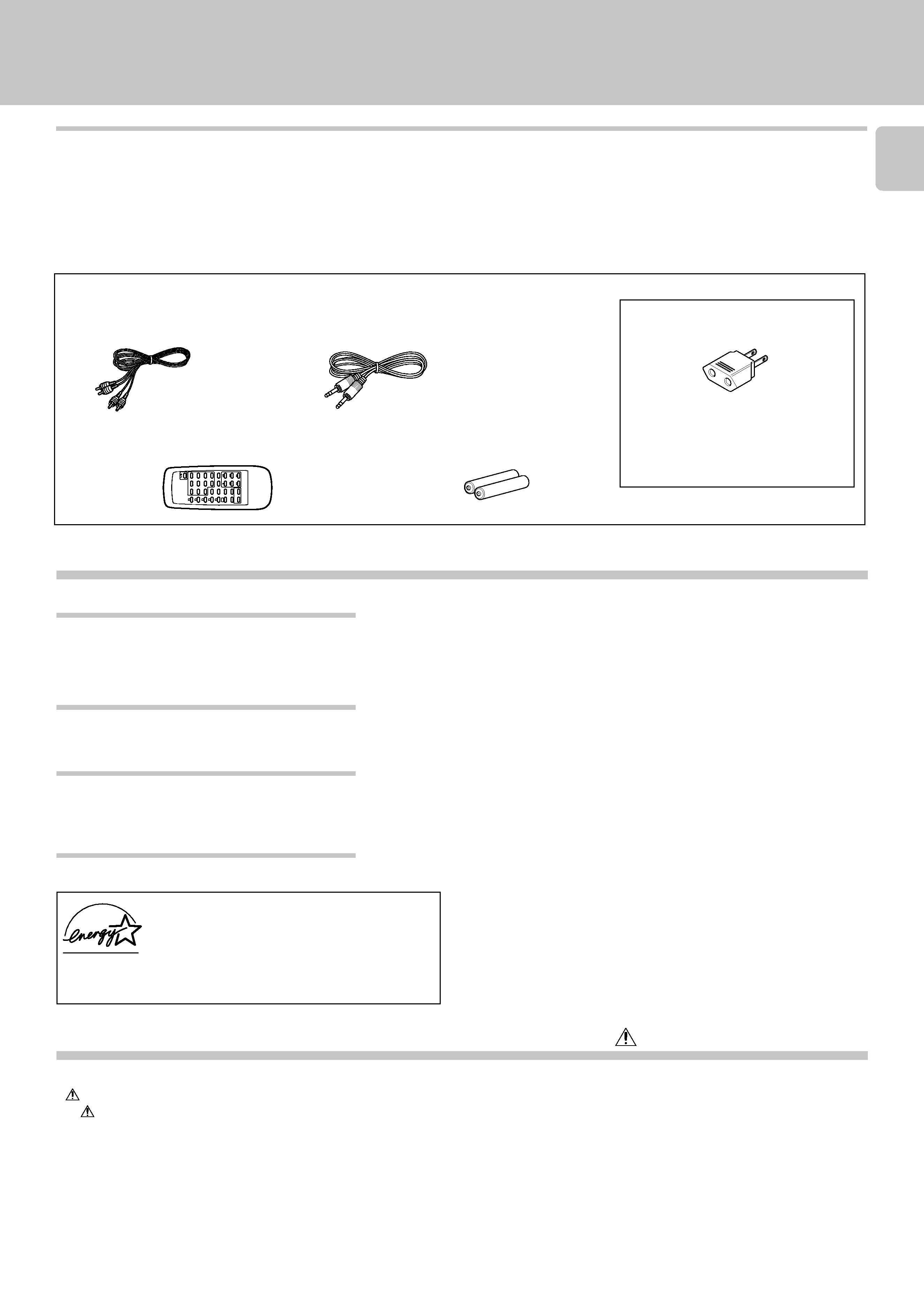
Audio cord ............... (1)
System control cord ........... (1)
Remote control unit .............. (1)
Batteries (R6/AA) ................. (2)
(Except for CD-403/DPF-R3030)
(Except for CD-403/DPF-R3030)
AC plug adaptor .............. (1)
REMOTE
CONTROL
UNIT
RC-P0601
POWER
1
2
DOWN
UP
3
45
6
78
9
P.MODE
0
+10
TIME
DISP.
CLEAR
CHECK
SKIP
REPEAT
RANDOM
EDIT
DISC
SELECTOR
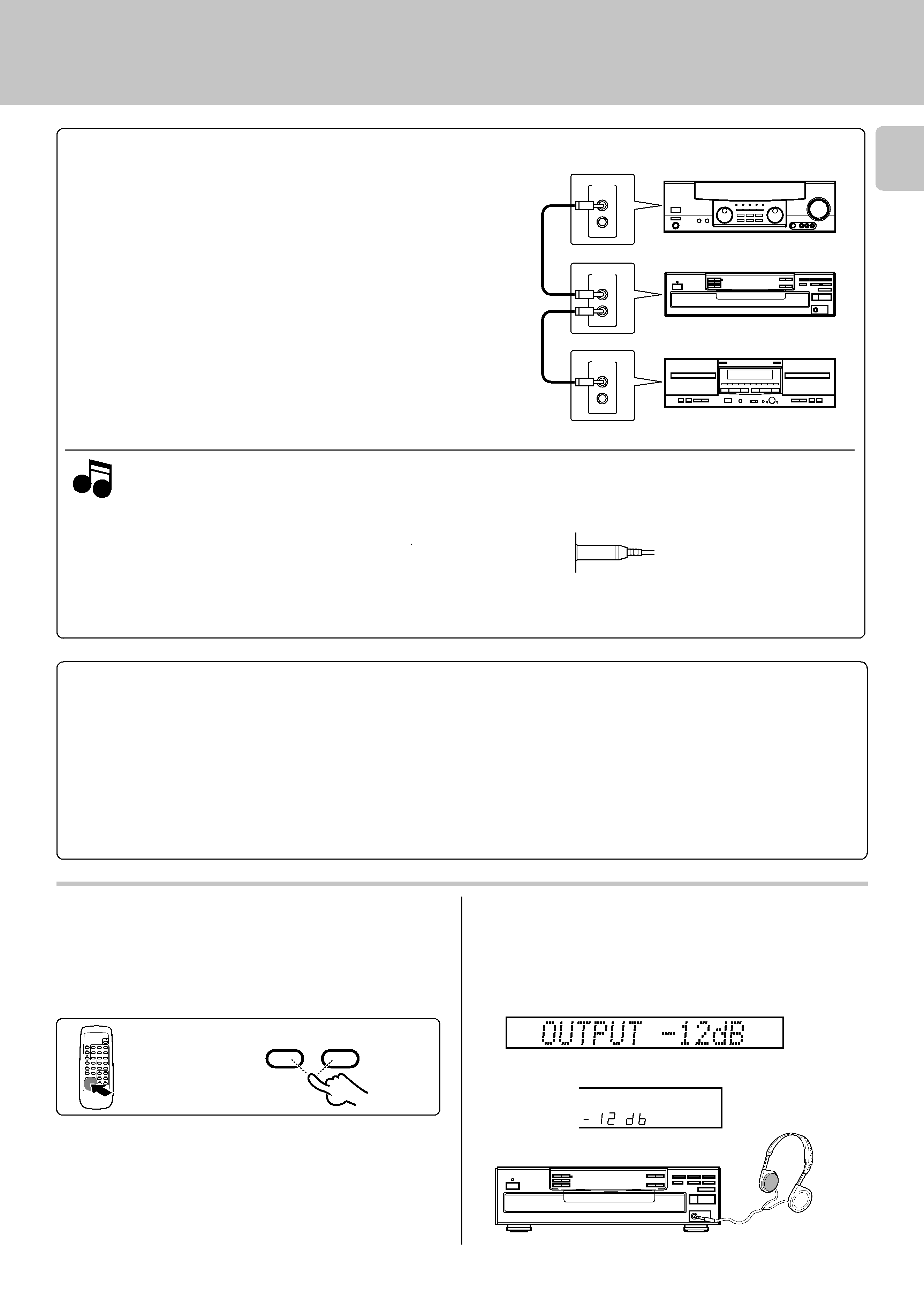
OUTPUT
5
4
3
1
2
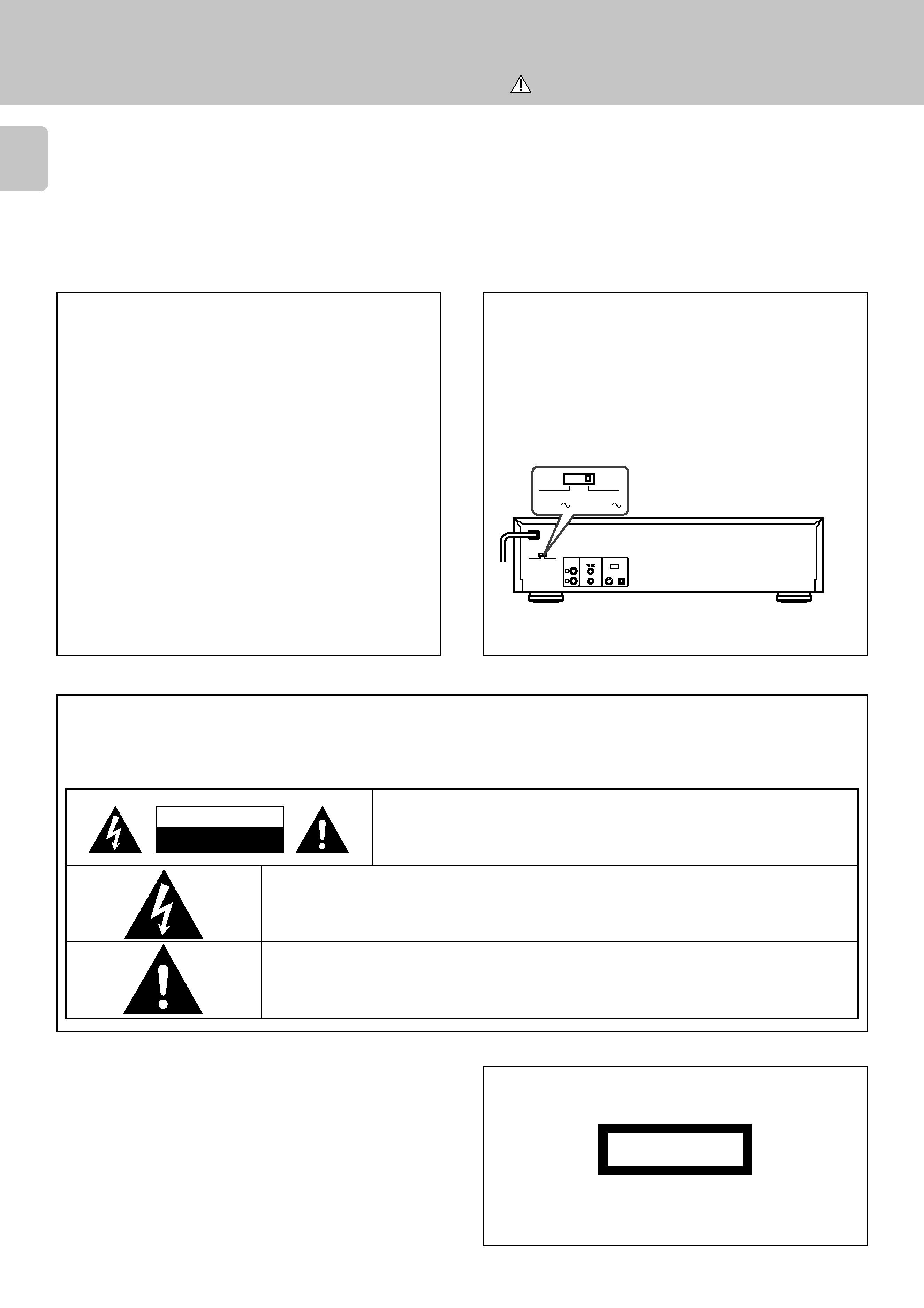
Caution: Read the pages marked
carefully to ensure safe operation.
Programmed play (PGM mode) ................................... 13
Playback in a random order (Random playback) ....... 16
Repeated playback ........................................................ 17
Editing ............................................................................. 19
Timer operations ........................................................... 21
Maintenance ................................................................... 22
In case of difficulty ........................................................ 23
Specifications ................................................................. 24
Before applying power ................................................... 2
Safety precautions ...................................................... 2
Unpacking .................................................................... 3
Special features ........................................................... 3
System connections ....................................................... 4
Controls and indicators .................................................. 6
Operation of remote control unit ................................. 8
Preparing to play tracks ................................................. 9
Normal play (TRACK mode) ........................................ 10
Displays .......................................................................... 12
¶ The text information such as disc title or track title (up to 1000 letters) recorded on the CDs
can be easily called and displayed in alphanumerics. (Some
words and text may not be displayed.)
@
¶ D.R.I.V.E. (Dynamic Resolution Intensive Vector Enhancement) IC is built in for drastic
reduction of distortion at small signal level.
¶ Edit mode is the function for rearranging tracks according to the tape length so that no
music is interrupted in the middle.
(
¶ Auto space function.
%
¶ Easy operation functions allow systematic operation with other KENWOOD components
connected through the system control connection.
5
Before applying power
Special features
Contents
CD-TEXT support (CD-406/DPF-R6030 only)
Advanced technologies incorporated in pursuit of im-
proved sound quality and stability (CD-406/DPF-R6030
only)
Convenient features for dubbing CD onto tape
Easy operation functions
Accessories
Use to adapt the plug on the power cord
to the shape of the wall outlet.
(Accessory only for regions where use
is necessary.)
As an
ENERGY STAR® Partner, Kenwood Corpora-
tion has determined that this products meets the
ENERGY STAR® guidelines for energy efficiency.
This product can save energy. Saving energy reduces air pollution and
lowers utility bills.
Unpacking