CANON NP6251 Service Manual

Cover page of CANON NP6251 Service Manual

Service Manual for CANON NP6251, downloadable as a PDF file.

Manual details

  • Immediate download after payment.
  • Delivered as a PDF file.
  • The manual has 812 pages
  • File size: 10.15 MB
  • Available language versions: Japanese, English
  • Different language versions may vary sligthly in file size and page count.

We guarantee that...

  • our manuals are complete,
  • the manual includes circuit diagrams,
  • our manuals are checked with antivirus,
  • We'll issue refund if the manual is damaged, incomplete or unreadable (our refund policy)

Sample pages

Thumbnail of page 1Thumbnail of page 2Thumbnail of page 3Thumbnail of page 4
Thumbnail of page 5Thumbnail of page 6Thumbnail of page 7Thumbnail of page 8
Thumbnail of page 9
background image
SERVICE
MANUAL
REVISION 0
FY8-13F0-000
JULY 1997
COPYRIGHT © 1997 CANON INC.
CANON NP6350/NP6251 REV.0 JULY 1997 PRINTED IN JAPAN (IMPRIMÉ AU JAPON)
background image
SERVICE
MANUAL
REVISION 0
FY8-13F0-000
JULY 1997
COPYRIGHT © 1997 CANON INC.
CANON NP6350/NP6251 REV.0 JULY 1997 PRINTED IN JAPAN (IMPRIMÉ AU JAPON)
background image
IMPORTANT
THIS DOCUMENTATION IS PUBLISHED BY CANON INC., JAPAN, TO SERVE AS A SOURCE OF
REFERENCE FOR WORK IN THE FIELD.
SPECIFICATIONS AND OTHER INFORMATION CONTAINED HEREIN MAY VARY SLIGHTLY FROM
ACTUAL MACHINE VALUES OR THOSE FOUND IN ADVERTISING AND OTHER PRINTED
MATTER.
ANY QUESTIONS REGARDING INFORMATION CONTAINED HEREIN SHOULD BE DIRECTED TO
THE COPIER SERVICE DEPARTMENT OF THE SALES COMPANY.
THIS DOCUMENTATION IS INTENDED FOR ALL SALES AREAS, AND MAY CONTAIN
INFORMATION NOT APPLICABLE TO CERTAIN AREAS.
COPYRIGHT © 1997 CANON INC.
Printed in Japan
Imprimé au Japon
Use of this manual should be
strictly supervised to avoid
disclosure
of
confidential
information.
Prepared by
OFFICE IMAGING PRODUCTS TECHNICAL SUPPORT DEPARTMENT 1
OFFICE IMAGING PRODUCTS TECHNICAL SUPPORT DIVISION
CANON INC.
5-1, Hakusan 7-chome, Toride-shi, Ibaraki 302 Japan
COPYRIGHT © 1997 CANON INC.
CANON NP6350/NP6251 REV.0 JULY 1997 PRINTED IN JAPAN (IMPRIMÉ AU JAPON)
background image
COPYRIGHT © 1997 CANON INC.
CANON NP6350/NP6251 REV.0 JULY 1997 PRINTED IN JAPAN (IMPRIMÉ AU JAPON)
i
This Service Manual contains basic data and figures on the plain paper copier
NP6350/NP6251 needed to service the machine in the field.
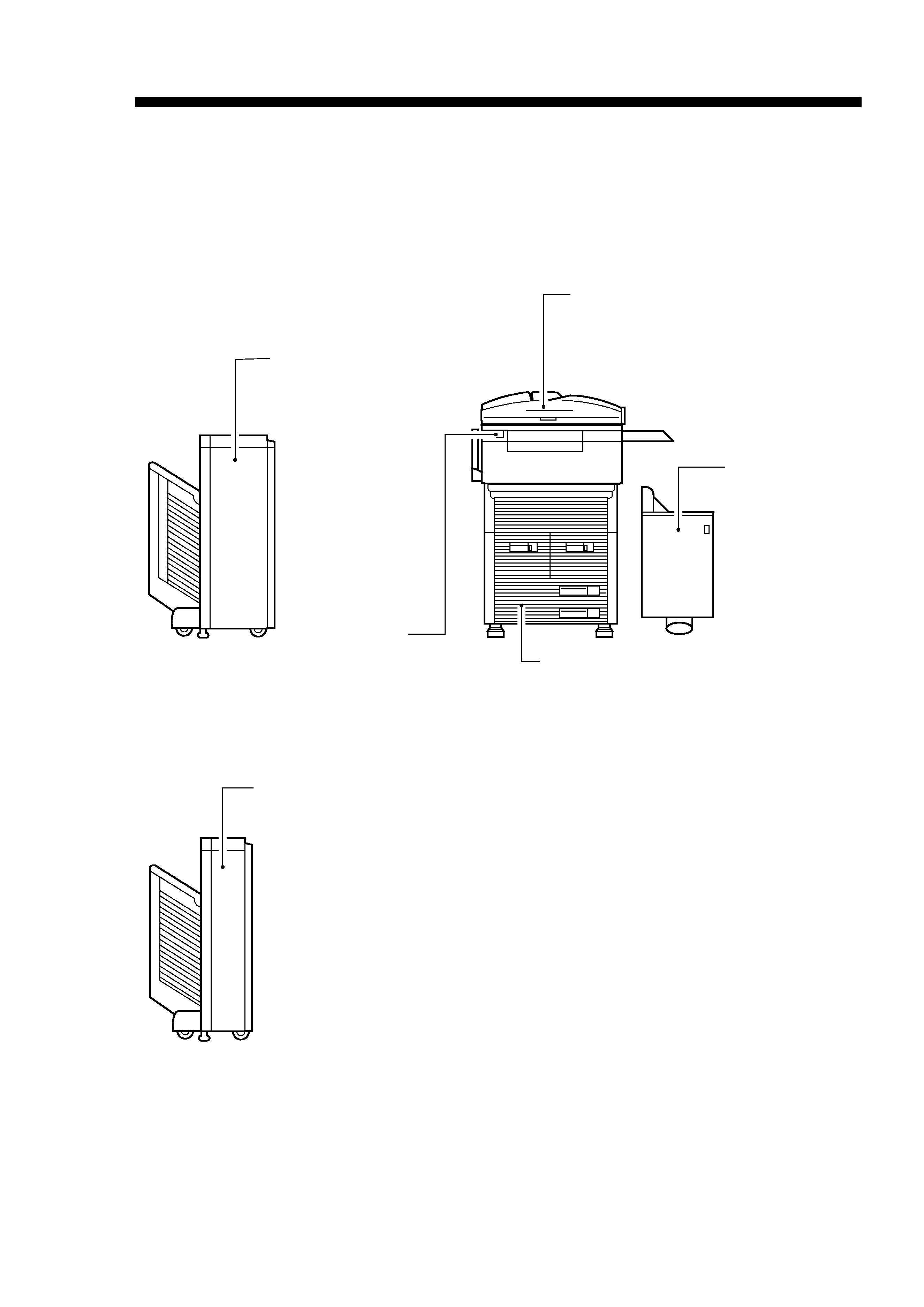
The NP6350/NP6251 is designed to enable full automatic copying work, and comes
with the following systems accessories:
1. Stapler Sorter-E2
2. RDF-D1
3. Paper Deck-A1
4. Sorter-G1
This Service Manual covers the copier only, and consists of the following chapters:
Chapter 1
General Description introduces the copier's features and specifications,
shows how to operate the copier, and explains how copies are made.
Chapter 2
Basic Operation provides outlines of the copier's various mechanical
workings.
Chapter 3
Exposure System discusses the principles of operation used for the
copier's lens drive unit and scanner drive unit. It also explains the timing
at which these drive units are operated, and shows how they may be
disassembled/assembled and adjusted.
Chapter 4
Image Formation System discusses the principles of how images are
formed. It also explains the timing at which the various units involved in
image formation are operated, and shows how they may be
disassembled/assembled and adjusted.
Chapter 5
Pick-Up/Feeding System explains the principles used from when copy
paper is picked up to when a copy is delivered in view of the functions of
electrical and mechanical units and in relation to their timing of operation.
It also shows how these units may be disassembled/assembled and
adjusted.
Chapter 6
Fixing System explains the principles used to fuse toner images to
transfer media in view of the functions of electrical and mechanical units
and in relation to their timing of operation. It also shows how these units
may be disassembled/assembled and adjusted.
Chapter 7
Externals/Auxiliary Mechanisms shows the copier's external parts, and
explains the principles used for the copier's various control mechanisms
in view of the functions of electrical and mechanical units and in relation
to their timing of operation. It also shows how these units may be
disassembled/assembled and adjusted.
Chapter 8
Paper Deck-A1 explains the principles used from when copy paper is
picked up to when a copy is delivered in view of the functions of electrical
and mechanical units and in relation to their timing of operation. It also
shows how these units may be disassembled/assembled and adjusted.
Chapter 9
Installation introduces requirements for the site of installation, and shows
how the copier may be installed using step-by-step instructions.
Chapter 10
Maintenance and Servicing provides tables of periodically replaced parts
and consumables/durables and scheduled servicing charts.
INTRODUCTION
background image
Chapter 11
Troubleshooting provides tables of maintenance/inspection,
standards/adjustments, and problem identification (image
fault/malfunction).
Appendix contains a general timing chart and general circuit diagrams.
The following rules apply throughout this Service Manual:
1. Each chapter contains sections explaining the purpose of specific functions and the
relationship between electrical and mechanical systems with reference to the
timing of operation.
In the diagrams,
represents the path of mechanical drive--where a
signal name accompanies the symbol
, the arrow indicates the direction
of the electric signal.
The expression "turn on the power" means flipping on the power switch, closing the
front door, and closing the delivery unit door, which results in supplying the machine
with power.
2. In the digital circuits, `1' is used to indicate that the voltage level of a given signal
is "High," while `0' is used to indicate "Low." (The voltage value, however, differs
from circuit to circuit.)
In practically all cases, the internal mechanisms of a microprocessor cannot be
checked in the field. Therefore, the operations of the microprocessors used in the
machines are not discussed: they are explained in terms of from sensors to the
input of the DC controller PCB and from the output of the DC controller PCB to the
loads.
The descriptions in this Service Manual are subject to change without notice for
product improvement or other purposes, and major changes will be communicated in the
form of Service Information bulletins.
All service persons are expected to have a good understanding of the contents of this
Service Manual and all relevant Service Information bulletins and be able to identify and
isolate faults in the machine.
COPYRIGHT © 1997 CANON INC.
CANON NP6350/NP6251 REV.0 JULY 1997 PRINTED IN JAPAN (IMPRIMÉ AU JAPON)
ii
background image
System Configuration
The NP6350/NP6251 is designed to accommodate the following accessories:
COPYRIGHT © 1997 CANON INC.
CANON NP6350/NP6251 REV.0 JULY 1997 PRINTED IN JAPAN (IMPRIMÉ AU JAPON)
iii
Stapler Sorter-E2
RDF-D1
NP6350/NP6251
(front paper deck + cassette type)
Paper Deck-A1
Sorter G1
Control Card V
It feeds a stack of originals to
the copier, sheet by sheet.
It allows control of
copy volume.
It can automatically sort
and group copies.
It can accommodate
as many as 3,500
sheets of
A4/B5/LTR paper.
In addition to the
functions of the 20-Bin
Stapler Sorter, it can
automatically staple
sorted copies.
It also is equipped with
a front access function,
in which copies may be
removed from the front,
and a multiple stacking
function, in which two or
more sets may be
delivered in a single bin.

Reviews

There are no reviews of this manual yet.