TEAC AG-D7900 Service Manual

Cover page of TEAC AG-D7900 Service Manual

Service Manual for TEAC AG-D7900, downloadable as a PDF file.

We also have owner's manual to this model.

Manual details

  • Immediate download after payment.
  • Delivered as a PDF file.
  • The manual has 34 pages
  • File size: 4.04 MB
  • Available language versions: English
  • Different language versions may vary sligthly in file size and page count.

We guarantee that...

  • our manuals are complete,
  • the manual includes circuit diagrams,
  • our manuals are checked with antivirus,
  • We'll issue refund if the manual is damaged, incomplete or unreadable (our refund policy)

Sample pages

Thumbnail of page 1Thumbnail of page 2Thumbnail of page 3Thumbnail of page 4
Thumbnail of page 5Thumbnail of page 6Thumbnail of page 7Thumbnail of page 8
Thumbnail of page 9
background image
A
AG
G--D
D779
90
00
0
SERVICE MANUAL
AV Digital Home Theater Receiver
Effective : February, 2002
S-0000A
NOTES
PC boards shown are viewed from parts side.
The parts with no reference number or no parts number in the
exploded views are not supplied.
As regards the resistors and capacitors, refer to the circuit diagrams
contained in this manual.
£
Parts marked with this sign are safety critical components. They
must be replaced with identical components - refer to the appropriate
parts list and ensure exact replacement.
background image
2
CONTENTS
SPECIFICATIONS .................................................................................................................................3
SAFETY INSTRUCTIONS ...................................................................................................................4
MEASUREMENTS AND ADJUSTMENTS ........................................................................................5
FIP DISPLAY ........................................................................................................................................8
DISPLAY PIN CONNECTION ..............................................................................................................9
IC BLOCK DIAGRAMS AND PIN FUNCTIONS ................................................................................10
EXPLODED VIEWS AND PARTS LIST .............................................................................................22
PC BOARDS AND PARTS LIST ........................................................................................................ 24
INCLUDED ACCESSORIES ...............................................................................................................30
background image
3
Amplifier Section
Surround Output Power (0.9 % THD, 1 kHz, 8 ohms):
60 + 60 watts (Front)
60 watts (Center)
60 + 60 watts (Rear)
Delay Time:
DOLBY DIGITAL: REAR 0 ­ 15 ms
CENTER 0 ­ 5 ms
DOLBY PRO LOGIC: REAR 15 ­ 30 ms
Audio Input Sensitivity/Impedance:
*LINE: 220 mV/47 k ohms
Output Level/Impedance:
CD-R/TAPE REC: 200 mV/2.2 k ohms
Frequency Response:
*LINE: 20 Hz ­ 65 kHz, +1/ ­3 dB
Signal-to-Noise Ratio:
*LINE: 95dB (IHF-A)
Tone Control:
BASS: ± 10 dB at 100 Hz
TREBLE: ± 10 dB at 10 kHz
Digital Audio Section
Sampling Frequency: 32 kHz, 44.1 kHz, 48 kHz, 96 kHz
DIGITAL Input Level/Impedance:
DIGITAL 1, 2 (OPTICAL): ­15 dBm -- ­21 dBm
DIGITAL 3 (COAXIAL): 0.5 Vp-p / 75 ohms
FM Tuner Section
(Without notes 100.1 MHz, 65 dBf)
Tuning Range:
87.5 MHz ­ 108.0 MHz (100 kHz steps)
Usable Sensitivity (IHF):
Mono: 11.2 dBf
50 dB Quieting Sensitivity:
Mono: 15.3 dBf
Stereo: 38.5 dBf
Capture Ratio: 2.0 dB
Image Rejection Ratio: 45 dB
AM Suppression Ratio: 55 dB
Total Harmonic Distortion (1 kHz):
Mono: 0.4%
Stereo: 0.5%
Frequency Response: 30 Hz ­ 15 kHz, +1/ ­1.5 dB
Stereo Separation (1 kHz): 40 dB
Signal-to-Noise Ratio:
Mono: 75 dB
Stereo: 70 dB
AM Tuner Section
Tuning Range:
530 kHz ­ 1,720 kHz (10 kHz steps)
Usable Sensitivity: 55 dB/m
Total Harmonic Distortion: 0.8% at 85 dB/m
Signal-to-Noise Ratio: 45 dB at 85 dB/m
Video Section
Input Sensitivity/Impedance: 1.0 Vp-p/75 ohms
Output Level/Impedance: 1.0 Vp-p/75 ohms
General
Power Requirements:
120 V AC, 60 Hz (U.S.A./ Canada model)
120/230 V AC, 50-60Hz (General Export model)
Power Consumption:
2.5 A
AC Outlets:
Switched x 2, Total 100 W max. (1 A max.)
Dimensions (W x H x D)
435 x 165 x 350 mm (17-1/8" x 6-1/2" x 13-3/4")
Weight (net):
8.2kg (18-1/16lbs) (U.S.A./ Canada model)
8.4kg (18-1/2lbs) (General Export model)
Standard Accessories:
AM Loop Antenna x 1
FM T-type Antenna x 1
Remote Control Unit (UR-417) x 1
* LINE means CD, CD-R/TAPE, VCR/VIDEO 1, DBS/VIDEO 2,
DVD/VIDEO 3 and AUX/VIDEO 4.
< Improvements may result in specifications and features
changing without notice.
< Illustrations may differ slightly from production models.
SPECIFICATIONS
background image
4
SAFETY INSTRUCTIONS
PRECAUTIONS DURING SERVICING
1. Parts identifide by the
( )symbol parts are critical
for safety. Replace only with parts number specified.
2. In addition to safety, other parts and assemblies are
specified for conformance with such regulations as
those applying to spurious radiation.
These must also be replaced only with specifide
replacements.
Examples :RF converters, tuner units, antenna
selectswitches, RF cables, noise blocking capacitors,
noise blocking filters, etc.
3. Use specified internal wiring. Note especially :
1) Wires covered with PVC tubing
2) Double insulated wires
3) High voltage leads
4. Use specified insulating materials for hazardous live
parts. Note especially:
1) Insulation Tape
2) PVC tubing
3) Spacers(insulating barriers)
4) Insulation sheets for transistors
5) Plastic screws for fixing micro switches
5. When replacing AC primary side components
(transformers, power cords, noise blocking
capacitors, etc.), wrap ends of wires securely about
the terminals before soldering.
6. Make sure that wires to do not contact heat
producing parts (heat sinks, oxide metal film
resistors, fusible resistors, etc.).
7. Check that replaced wires do not contact sharp
edged or pointed parts.
8. Also check areas surrounding repaired locations.
9. Make sure that foreign objects (screws, solder
droplets, etc.) do not remain inside the set.
MAKE YOUR CONTRIBUTION TO PROTECT
THE ENVIRONMENT
Used batteries with the ISO symbol for recycling
as well as small accumulators (rechargeable
batteries), mini-batteries (cells) and starter
batteries should not be thrown into the garbage
can.
Please leave them at an appropriate depot. All other house-
hold batteries can be thrown out with the household waste.
SAFETY CHECK AFTER SERVICING
After servicing, make measurements of leakage-current
or resistance in order to determine that exposed parts
are acceptably insulated from the supply circuit.
The leakage-current measurement should be done
between accessible metal parts (such as chassis,
ground terminal, microphone jacks, signal input/output
connectors, etc.) and the earth ground through a
resister of 1500 ohms paralleled with a 0.15
capacitor, under the unit's normal working conditions.
The leakage-current should be less than 0.5mA rms AC.
The resistance measurement should be done between
accessible exposed metal parts and power cord plug
prongs with the power switch (if included) "ON". The
resistance should be more than 2.2M Ohms.
PRECAUTIONS IN REPAIRING
When repairing or adjusting the unit, please note the
following points.
1. Do not put excessive pressure on the mechanical
part (operation part), including the pick-up block, as
extremely high mechanical precision is required in
these parts.
2. When the base is removed for repair adjustment,
make sure that there are no metal obiects in the
narrow gap between the P. C. board or the mecha
parts and the base
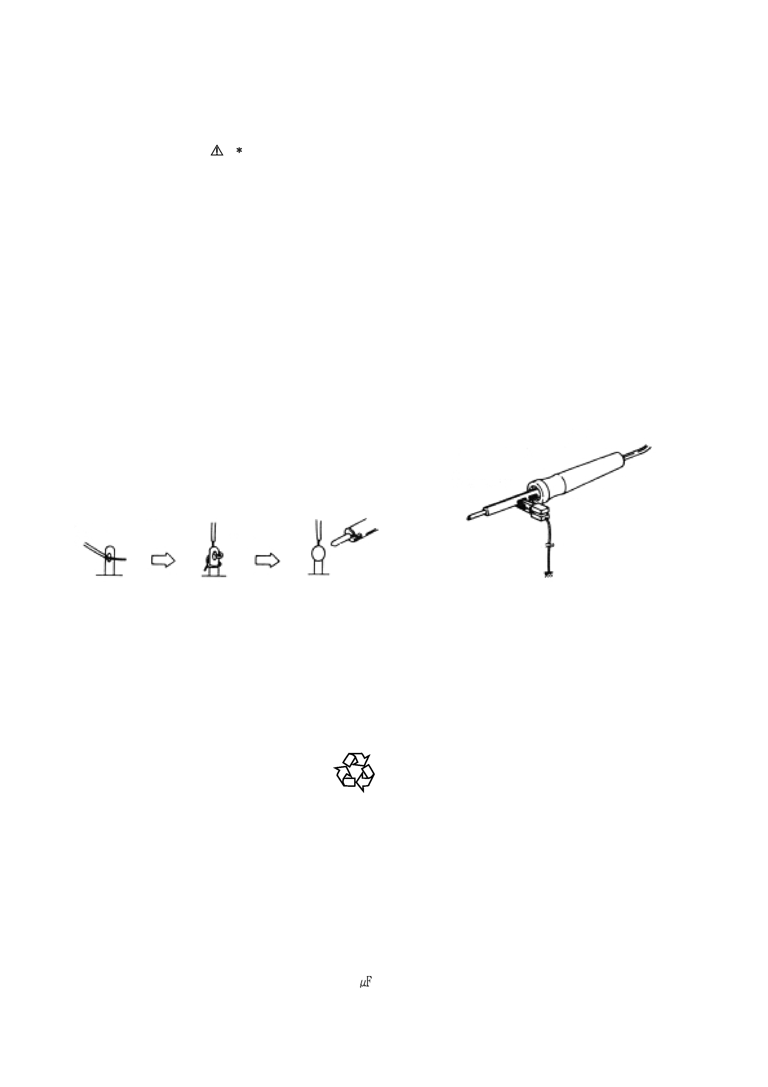
3. The Micro-Computer and the CD signal processing
ICs can be damaged by static electricity or leakage
from a soldering iron during repairing. While
soldering, please take the precautions against
leakage as in the illustration.
4. Do not loosen any screws in the pick-up block.
When handing the pick-up block, please refer to the
points to NOTE when replacing the pick-up block.
5. Keep safety for hazardous invisible Laser Radiation,
DO NOT watch the Laser Beam (Objective lens)
directly.
6. Models for some countries, laser warning labels are
affixed on the unit and inside of the unit, as shown
below. Read it carefully for your safety, when
repairing or adjusting the unit.
GND
background image
ALIGNMENT INSTRUCTIONS
EQUIPMENT NEEDED:
AM Signal Generator
FM Signal Generator
Oscilloscope
VTVM(AC, DC)
Test loop antenna (AM Adjustment)
Dummy antenna (FM Adjustment)
Distortion analyser
IMPORTANT
1. Check power-source voltage.
2. Set the function switch to band aligned.
3. Keep the signal input as low as possible to adjust accurately.
4. Modulation and modulation frequency.
Item
Modulation
Modulation frequency
Band
AM
30%
400Hz
FM
400Hz
ADJUSTMENT POINT
MEASUREMENTS AND ADJUSTMENTS
100% (40 kHz Dev.) [E/UK]
100% (75 kHz Dev.) [US]
AM LOOP ANT
ANT TERMINAL
CT10
PACK1
IC11
J208
VR11
VR13
IC12
T102
FM ANT
VR12
J207
J205
L104
L105
T101
<PACK DETAIL>
(FOR UL version)
L3
L7
L4
L5
L6
L3
L7
T1
L6
L4
L5
L3
L6
L4
FM OSC COIL
T1
FM IFT
FM OFFSET ADJ TP
CT10
AM ANT TRIMMER (1503kHz/1510kHz)
L104
AM ANT COIL
L105
AM OSC COIL
T101
FM IFT COIL
T102
AM IFT COIL (612kHz/610kHz)
VR13
FM SD ADJUSTMENT
VR12
AM SD ADJUSTMENT
VR11
FM SEPARATION ADJ
J208
FM/AM VT
J205
J207
FM ANT COIL
FM RF COIL
(FOR EUR version)
L1
L2
L6
L3
L4
L5
L1
L2
L5
L7
IFT
FM OSC COIL
L7
FM ANT COIL
FM RF COIL
5

Reviews

There are no reviews of this manual yet.