TEAC AG-680 Owner's Manual

Cover page of TEAC AG-680 Owner's Manual

Owner's Manual for TEAC AG-680, downloadable as a PDF file.

We also have service manual to this model.

Manual details

  • Immediate download after payment.
  • Delivered as a PDF file.
  • The manual has 92 pages
  • File size: 2.84 MB
  • Available language versions: French, English, Spanish, German, Italian
  • Different language versions may vary sligthly in file size and page count.

We guarantee that...

  • our manuals are complete,
  • our manuals are checked with antivirus,
  • We'll issue refund if the manual is damaged, incomplete or unreadable (our refund policy)

Sample pages

Thumbnail of page 1Thumbnail of page 2Thumbnail of page 3Thumbnail of page 4
Thumbnail of page 5Thumbnail of page 6Thumbnail of page 7Thumbnail of page 8
Thumbnail of page 9
background image
ag-680
`
AM/FM Stereo Receiver
9A07125400
This appliance has a serial number located
on the rear panel. Please record the model
number and serial number and retain them
for your records.
Model number
Serial number
WARNING: TO PREVENT FIRE OR SHOCK
HAZARD, DO NOT EXPOSE THIS
APPLIANCE TO RAIN OR MOISTURE.
The exclamation point within an equilateral triangle is intended to alert the user to the
presence of important operating and maintenance (servicing) instructions in the literature
accompanying the appliance.
The lightning flash with arrowhead symbol, within an equilateral triangle, is intended to alert
the user to the presence of uninsulated "dangerous voltage" within the product's enclosure
that may be of sufficient magnitude to constitute a risk of electric shock to persons.
CAUTION: TO REDUCE THE RISK OF ELECTRIC SHOCK, DO NOT
REMOVE COVER (OR BACK). NO USER-SERVICEABLE PARTS INSIDE.
REFER SERVICING TO QUALIFIED SERVICE PERSONNEL.
Ü
ÿ
Y
OWNER'S MANUAL........................................... 2
MANUEL DUPROPRIETAIRE ......................... 20
BEDIENUNGSANLEITUNG .............................. 38
MANUALE DI ISTRUZIONI.............................. 56
MANUAL DEL USUARIO................................. 74
Thanks for buying a TEAC.
Read this manual carefully to get the best performance from
this unit.
Nous vous remercions pour l'achat d'un appareil TEAC.
Lire ce manuel avec attention pour obtenir les meilleures
performances possibles de cet appareil.
Vielen Dank für den Kauf dieses TEAC-Geräts.
Bitte lesen Sie diese Anleitung sorgfältig durch, um die
Leistungsfähigkeit dieses Geräts optimal nutzen zu können.
Grazie per aver acquistato un prodotto TEAC.
Leggere attentamente questo manuale per ottenere le
migliori prestazioni da questo apparecchio.
Enhorabuena por la adquisición de un TEAC.
Lea detenidamente este manual a fin de obtener el mejor
rendimiento de esta unidad.
ENGLISH
FRANÇAIS
DEUTSCH
ITALIANO
ESPAÑOL
background image
­ 2 ­
CONTENTS
PRECAUTIONS
Choose the installation location of your unit carefully.
Avoid placing it in direct sunlight or close to a source
of heat. Also avoid locations subject to vibrations and
excessive dust, heat, cold or moisture.
The ventilation holes should not be covered. Make
sure there is at least 50 cm (20 inches) of space
above and at least 10 cm (4 inches) of space beside
the amplifier/receiver. Do not place a CD player or
other equipment on top of the amplifier/receiver.
Do not open the cabinet as this might result in
damage to the circuitry or electrical shock. If a
foreign object should get into the set, contact your
dealer.
When removing the power plug from the wall outlet,
always pull directly on the plug, never yank the cord.
Do not attempt to clean the unit with chemical
solvents as this might damage the finish. Use a
clean, dry cloth.
Keep this manual in a safe place for future reference.
Read This Before Operating
PRECAUTIONS ................................................................... 2
Read This Before Operating ......................................... 2
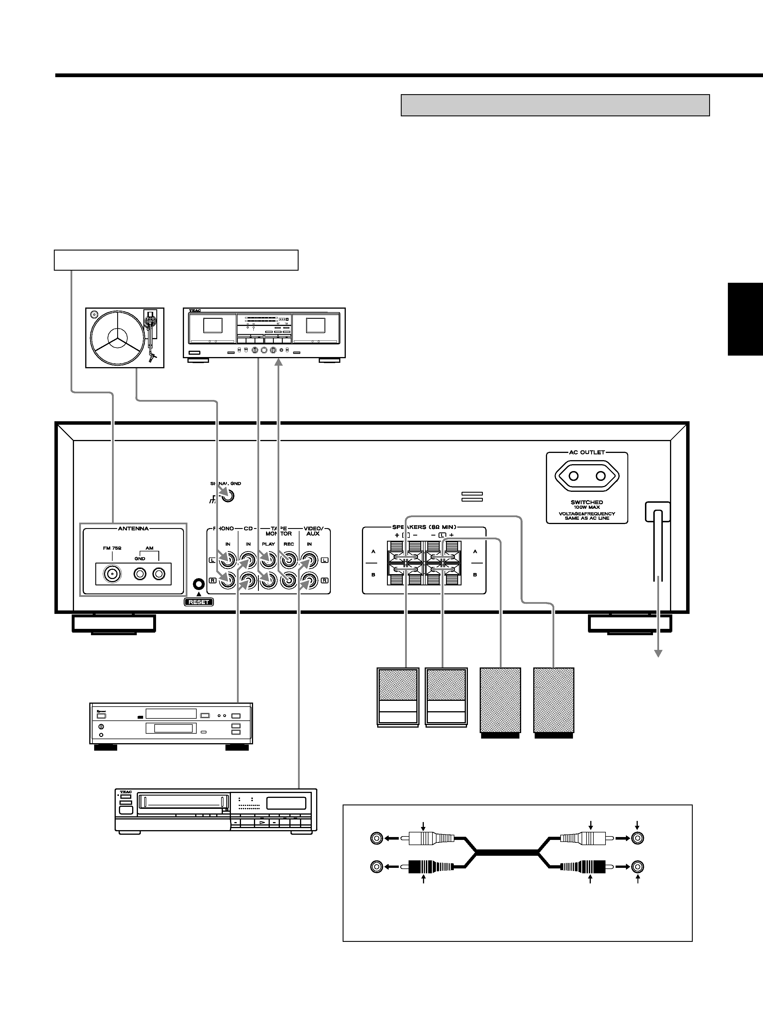
CONNECTIONS .................................................................. 3
Connecting Audio Equipment ...................................... 3
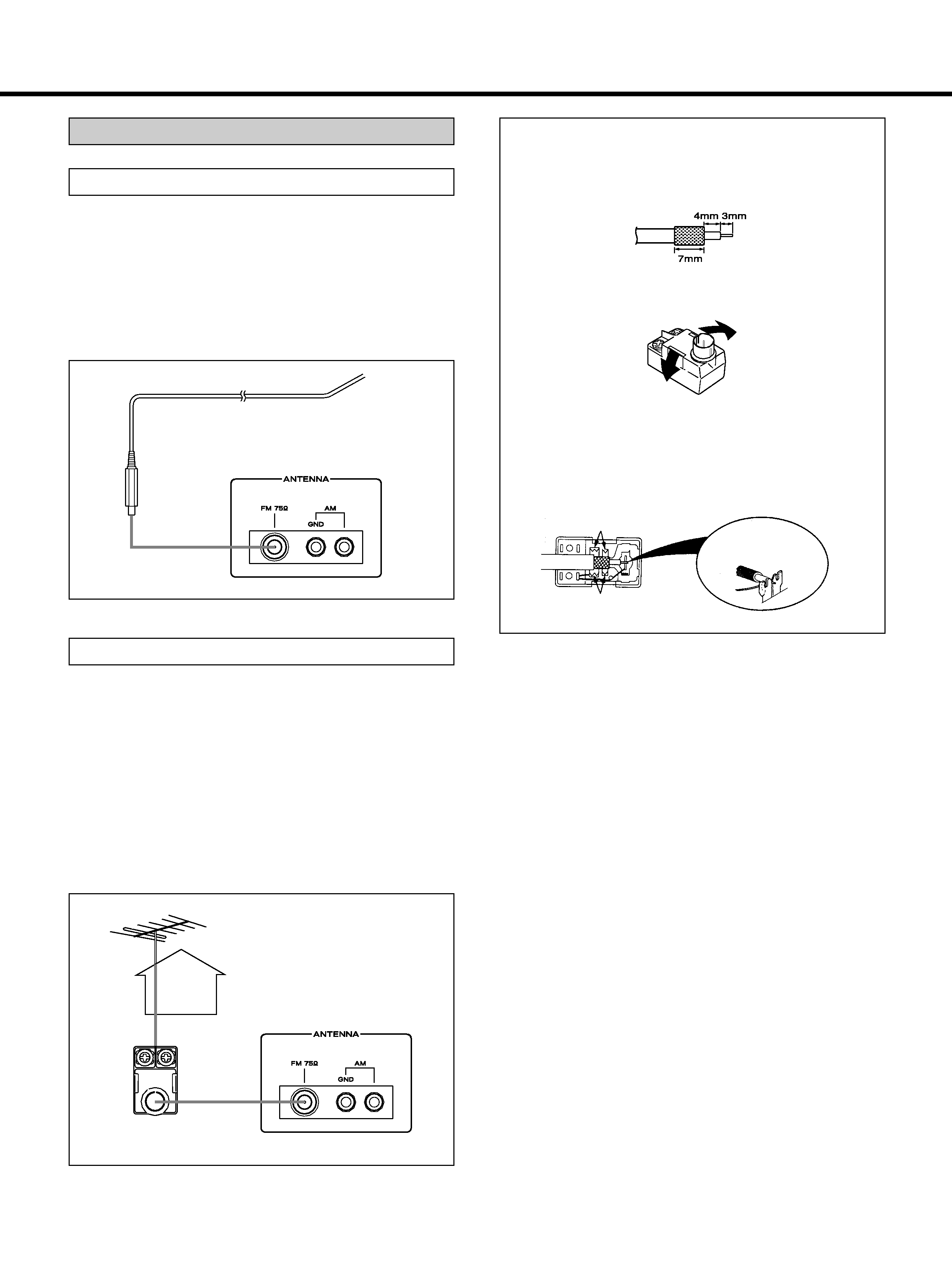
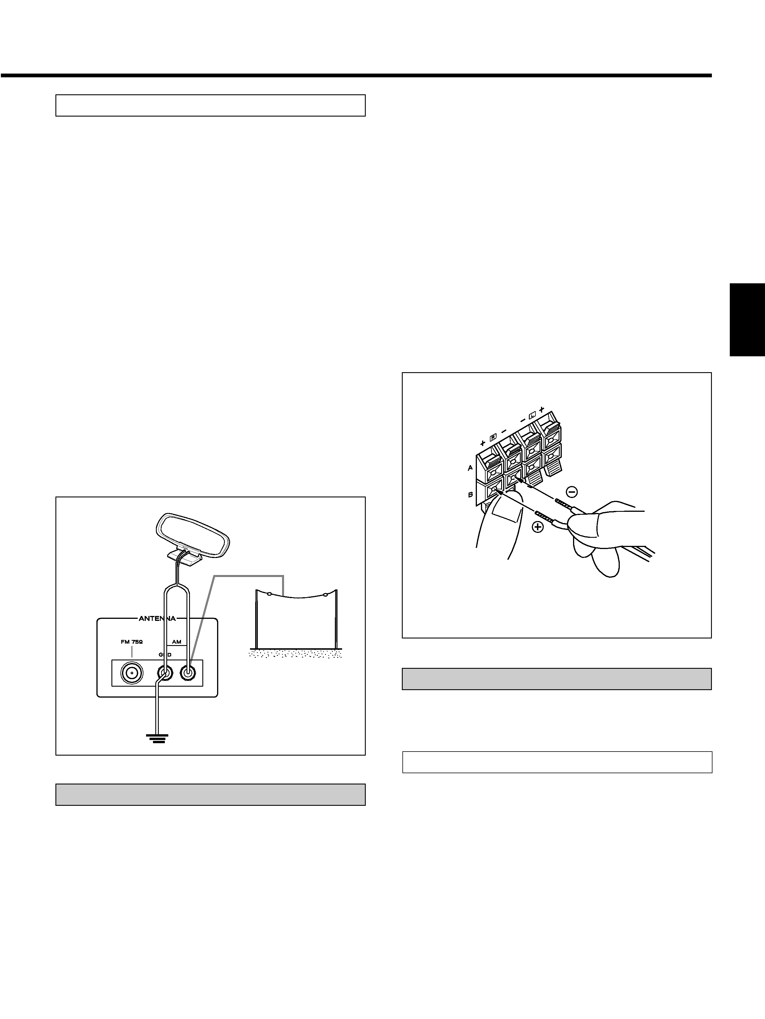
Connecting Antennas.................................................... 4
Connecting Speaker Systems ...................................... 5
Connecting the AC Power ............................................ 5
CONTROLS AND INDICATORS ........................................ 6
AUDIO OPERATIONS ........................................................ 8
Sleep Timer Operation ................................................. 8
Basic Operations ........................................................... 8
Radio Reception ............................................................ 9
Preset Tuning............................................................... 10
RDS (Radio data System) ........................................... 11
Playing Audio Sources ............................................... 13
Recording a Source..................................................... 14
MEMORY BACKUP FUNCTION ...................................... 14
Back-up Memory ......................................................... 14
REMOTE CONTROL UNIT ............................................... 15
Using the Remote Control Unit ................................. 15
Battery Installation ...................................................... 15
TEAC SYSTEM REMOTE-CONTROLLED
OPERATION...................................................................... 16
Using a CD Player and a Cassette Deck
with a REMOTE SENSOR Window ............................ 16
Buttons for the Operation of Other
TEAC Components ...................................................... 17
TROUBLESHOOTING ...................................................... 18
SPECIFICATIONS ............................................................. 19
IMPORTANT (for U.K. Customers)
DO NOT cut off the mains plug from this equipment.
If the plug fitted is not suitable for the power points
in your home or the cable is too short to reach a
power point, then obtain an appropriate safety
approved extension lead or consult your dealer.
If nonetheless the mains plug is cut off, remove the
fuse and dispose of the plug immediately, to avoid a
possible shock hazard by inadvertent connection to
the mains supply.
If this product is not provided with a mains plug, or
one has to be fitted, then follow the instructions
given below:
IMPORTANT. DO NOT make any connection to the
larger terminal which is marked with the letter E or
by the safety earth symbol
ç or coloured GREEN or
GREEN-and-YELLOW.
The wires in the mains lead on this product are
coloured in accordance with the following code:
BLUE:
NEUTRAL
BROWN:
LIVE
As these colours may not correspond with the
coloured markings identifying the terminals in
your plug proceed as follows:
The
wire
which
is
coloured
BLUE
must
be
connected to the terminal which is marked with the
letter N or coloured BLACK.
The wire which is coloured BROWN must be
connected to the terminal which is marked with the
letter L or coloured RED.
When replacing the fuse only a correctly rated
approved type should be used and be sure to re-fit
the fuse cover.
IF
IN
DOUBT
--
CONSULT
A
COMPETENT
ELECTRICIAN.
CAUTION Regarding Placement
(Except for U.S.A. and Canada)
To maintain proper ventilation, be sure to leave a
space around the unit (from the largest outer
dimensions including projections) equal to, or
greater than, shown below.
Left and Right Panels
: 10 cm
Rear Panel
: 10 cm
Top Panel
: 50 cm
background image
­ 3 ­
ENGLISH
CONNECTIONS
CAUTION:
... Do not plug the power cord of any component into AC
outlets and do not turn their POWER switches on
until all connections have been performed.
... The cable connectors should be fully inserted into the
jacks. Loose connections may cause hum and noise.
... Read the instructions for each component you intend
to use with the receiver.
+
­
L
L
R
R
White
White
White
Red
Red
Red
Audio connection cords
To make these connections, use interconnect cords with RCA
plugs. Make sure that you connect the white pin-plug to the white
jacks (left) and the red pin-plug to the red jacks (right).
Turntable
Speakers B
CD Player
Refer to "Connecting Antennas" on pages 4~5.
LINE
OUT
LINE
IN
Tape Deck
Speakers A
To AC outlet
Video Deck (VCR)
LINE
OUT
AUDIO
OUT
Connecting Audio Equipment
AUDIO signal jacks
PHONO IN jacks
Connect the turntable's output jacks to the PHONO IN
jacks.
CD IN jacks
Connect the CD player's output (LINE OUT) jacks to the
CD IN jacks.
TAPE MONITOR (PLAY/REC) jacks
Connect the cassette deck output (LINE OUT) jacks to
the PLAY jacks.
Connect the cassette deck input (LINE IN) jacks to the
REC jacks.
VIDEO/AUX jacks
Connect the video deck (VCR) LINE output (AUDIO
OUT) jacks to the VIDEO/AUX jacks.
background image
­ 4 ­
CONNECTIONS
How to connect a coaxial cable to the matching
transformer
1 Strip the cable and dress it as shown.
2 Press both side tabs outward to remove the
cover.
3 Wrap the core conductor around the central
metal fixture as shown. Crimp the jagged
metal fixtures so they hold the braided portion
using pliers, etc. Put the cover back in place.
FM Outdoor Antenna
In an area where FM signals are weak, it will be
necessary to use a 75-ohm unbalanced-type outdoor FM
antenna using the optional matching transformer, as
shown. Generally, a 3-element antenna will be
sufficient; if you live in an area where the FM signals
are particularly weak, it may be necessary to use one
with 5 or more elements.
Connect the coaxial cable of the antenna to the
matching transformer as shown. After completing
connection, plug the transformer into the "FM 75"
socket.
Outdoor FM Antenna
(75)
Matching Transformer
(optional)
FM Indoor Antenna
If you live reasonably close to a transmitter and want
to use the provided lead-type FM antenna, you will
have to connect it direct to the "FM 75" socket.
Fit the metal sleeve of the lead-type antenna over the
core (center) conductor of the "FM 75" socket, extend
the lead and fix it to a window frame or wall with
thumbtacks, or the like, where reception is best.
Lead-type FM Antenna (75) (provided)
Connecting Antennas
Jagged metal
Jagged metal
Insert into slit.
background image
­ 5 ­
ENGLISH
AM (MW) Antenna
Connecting Speaker Systems
AM Indoor Loop Antenna
A high-performance AM loop antenna provided with the
receiver is sufficient for good reception in most areas.
Connect the loop antenna's wires to the AM antenna
terminals as shown. Place the antenna on a shelf, for
example, or hang it on a window frame, etc., in the
direction which gives the best reception, as far away as
possible from the entire system, speaker cords and the
power cord, to prevent unwanted noise.
AM Outdoor Antenna
If the AM loop antenna provided does not deliver
sufficient reception (because you are too far from the
transmitter or in a concrete building, etc.), it may be
necessary to use an outdoor AM antenna. Use an
insulated wire more than 15 ft (5 m) long, strip one end,
and connect this to the terminal as shown. The antenna
wire should be strung outdoors or indoors near a
window. For better reception, connect the GND terminal
to a reliable ground.
Note:
Even when using an outdoor AM antenna, do not
disconnect the AM loop antenna.
Caution:
To avoid damaging the speakers by inputting a
sudden high-level signal, be sure to switch the power
off before connecting the speakers.
AM Loop Antenna
(provided)
AM Outdoor
Antenna
Connecting the AC Power
Be sure to connect the power cord to an AC outlet which
supplies the correct voltage.
How to connect the speaker cords
Press the lever, insert the stripped and twisted
end (approx. 10 mm) of the cord, then release
the lever so that the cord is held securely.
AC OUTLET
SWITCHED:
This socket switches on and off as you turn on and off
the receiver.
Caution:
The total power consumption of the components
connected to the AC OUTLET must not exceed 100W.
Connect the cable from each speaker to the
corresponding terminal on the rear of the receiver.
Most speaker cables have different markings, textures
or colors to help you tell the difference between
negative and positive.
Be sure to connect the positive (+) terminal on each
speaker to the positive (+) terminal on the receiver.
Similarly, connect the negative (­) terminal on the
speaker to negative (­) terminal on the receiver.
Notes:
Use speakers with a nominal impedance of 8 ohms
or more.
When attaching speakers, be sure to connect them to
both channels (L and R).
If speakers are connected to only A or B, no sound
will be heard from them if both SPEAKERS "A" and
"B" are selected.

Reviews

There are no reviews of this manual yet.