2
IIn
nttrro
od
du
uc
cttiio
on
n
Your new high fidelity receiver is designed to deliver
maximum enjoyment and years of trouble free service.
Please take a few moments to read this manual
thoroughly. It will explain the features and operation of
your unit and help ensure a trouble free installation.
Please unpack your unit carefully. We recommend that
you save the carton and packing material. They will be
helpful if you ever need to move your unit and may be
required if you ever need to return it for service. Your unit
is designed to be placed in a horizontal position and it is
important to allow at least two inches of space behind
your unit for adequate ventilation and cabling
convenience.
To avoid damage, never place the unit near radiators, in
front of heating vents, in direct sunlight, or in excessively
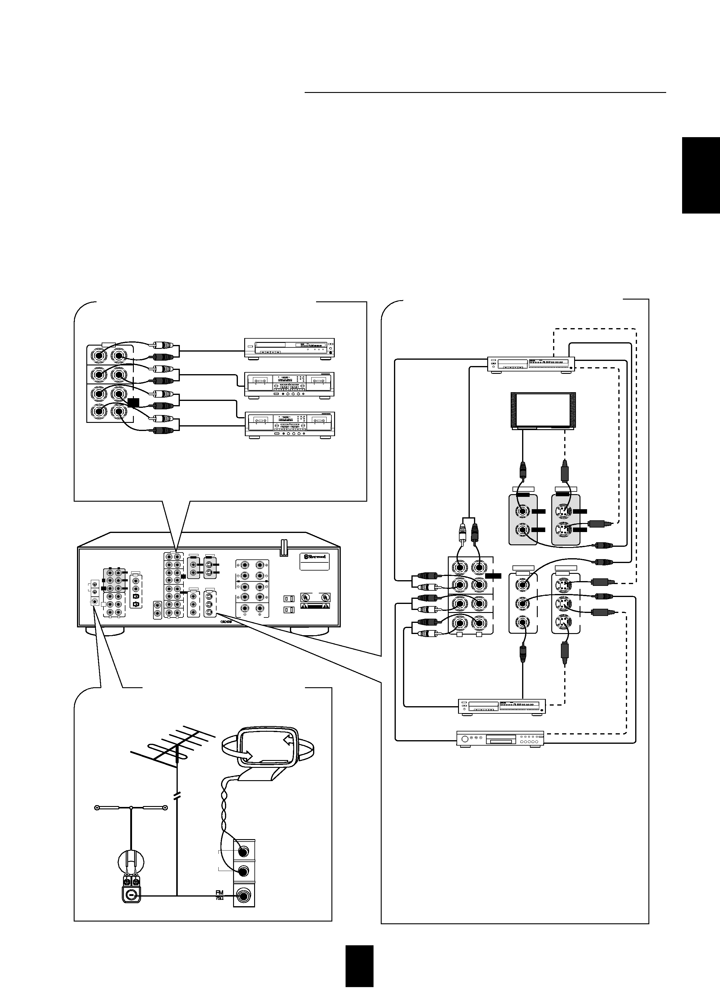
humid or dusty locations. Connect your complementary
components as illustrated in the following section.
C
CA
AU
UT
TIIO
ON
N :: T
TO
O R
RE
ED
DU
UC
CE
E T
TH
HE
E R
RIIS
SK
K O
OF
F
E
EL
LE
EC
CT
TR
RIIC
C S
SH
HO
OC
CK
K,, D
DO
O N
NO
OT
T
R
RE
EM
MO
OV
VE
E C
CO
OV
VE
ER
R ((O
OR
R B
BA
AC
CK
K))..
N
NO
O U
US
SE
ER
R--S
SE
ER
RV
VIIC
CE
EA
AB
BL
LE
E P
PA
AR
RT
TS
S
IIN
NS
SIID
DE
E.. R
RE
EF
FE
ER
R S
SE
ER
RV
VIIC
CIIN
NG
G T
TO
O
Q
QU
UA
AL
LIIF
FIIE
ED
D S
SE
ER
RV
VIIC
CE
E P
PE
ER
RS
SO
ON
NN
NE
EL
L..
C
CA
AU
UT
TIIO
ON
N
RISK OF ELECTRIC SHOCK
DO NOT OPEN
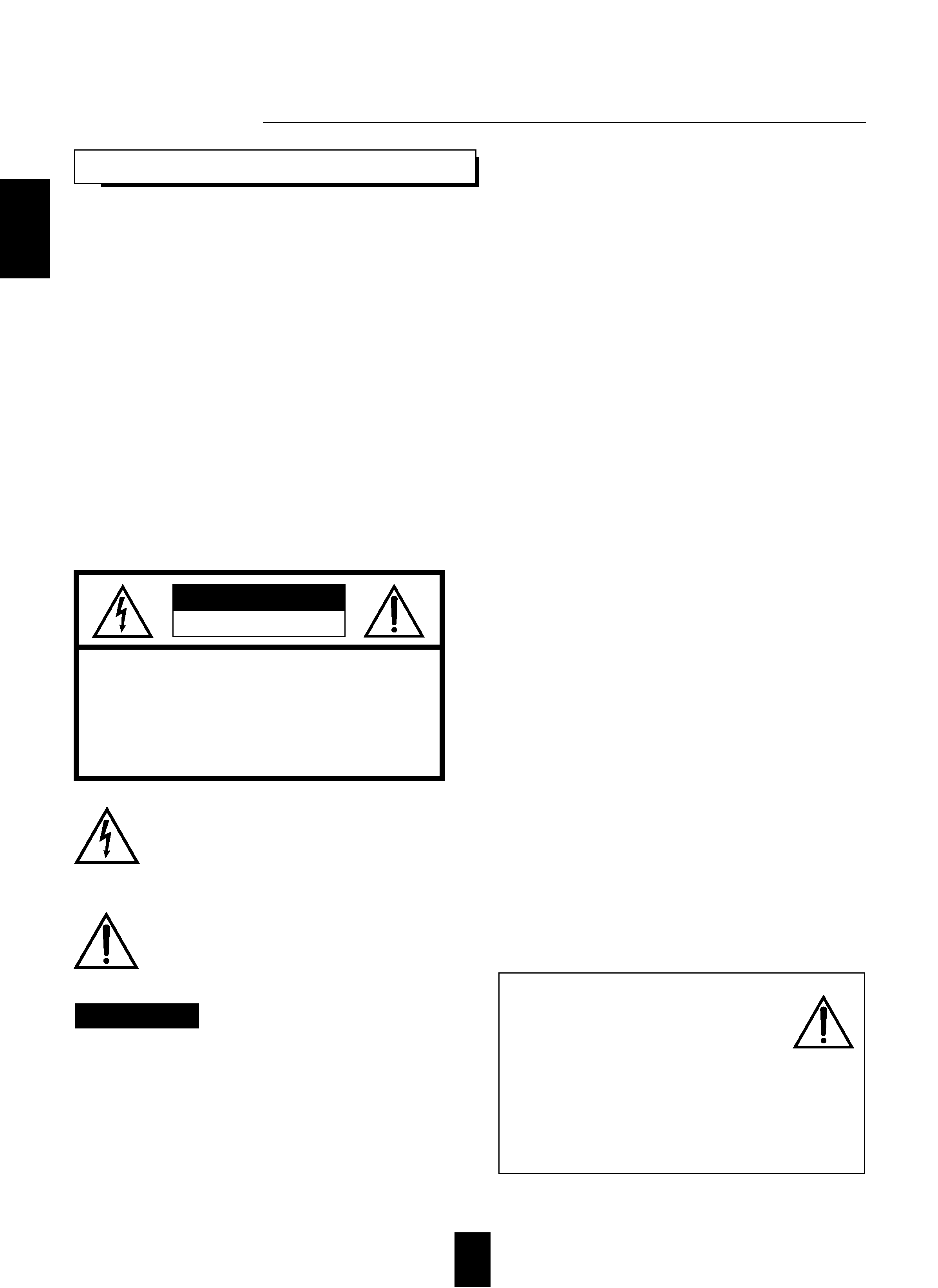
This symbol is intended to alert the user to the
presence of uninsulated "dangerous voltage"
within the product's enclosure that may be of
sufficient magnitude to constitute a risk of
electric shock to persons.
This symbol is intended to alert the user to the
presence of important operating and
maintenance (servicing) instructions in the
literature accompanying the appliance.
To reduce the risk of fire or electric shock, do not expose
this appliance to rain or moisture.
C
Ca
au
uttiio
on
n :: D
Do
o n
no
ott b
bllo
oc
ck
k v
ve
en
nttiilla
attiio
on
n o
op
pe
en
niin
ng
gs
s o
orr s
stta
ac
ck
k
o
otth
he
err e
eq
qu
uiip
pm
me
en
ntt o
on
n tth
he
e tto
op
p..
F
FO
OR
R U
U..S
S..A
A..
N
No
otte
e tto
o C
CA
AT
TV
V S
Sy
ys
stte
em
m IIn
ns
stta
alllle
err:: This reminder is
provided to call the CATV system installer's attention
to Article 820-40 of the NEC that provides guidelines
for proper grounding and, in particular, specifies that
the cable ground shall be connected to the
grounding system of the building, as close to the
point of cable entry as practical.
F
FC
CC
C IIN
NF
FO
OR
RM
MA
AT
TIIO
ON
N
This equipment has been tested and found to
comply with the limits for a Class B digital device,
pursuant to Part 15 of the FCC Rules. These limits
are designed to provide reasonable protection
against harmful interference in a residential
installation. This equipment generates, uses and can
radiate radio frequency energy and, if not installed
and used in accordance with the instructions, may
cause harmful interference to radio communications.
However, there is no guarantee that interference will
not occur in a particular installation. If this equipment
does cause harmful interference to radio or
television reception, which can be determined by
turning the equipment off and on, the user is
encouraged to try to correct the interference by one
or more of the following measures:
Reorient or relocate the receiving antenna.
Increase the separation between the equipment
and receiver.
Connect the equipment into an outlet on a circuit
different from that to which the receiver is
connected.
Consult the dealer or an experienced radio/TV
technician for help.
C
CA
AU
UT
TIIO
ON
N :: Any changes or modifications in
construction of this device which are not expressly
approved by the party responsible for compliance
could void the user's authority to operate the
equipment.
W
WA
AR
RN
NIIN
NG
G
UNPACKING AND INSTALLATION
C
Ca
au
uttiio
on
n rre
eg
ga
arrd
diin
ng
g p
plla
ac
ce
em
me
en
ntt
((E
Ex
xc
ce
ep
ptt ffo
orr U
U..S
S..A
A.. a
an
nd
d C
Ca
an
na
ad
da
a))
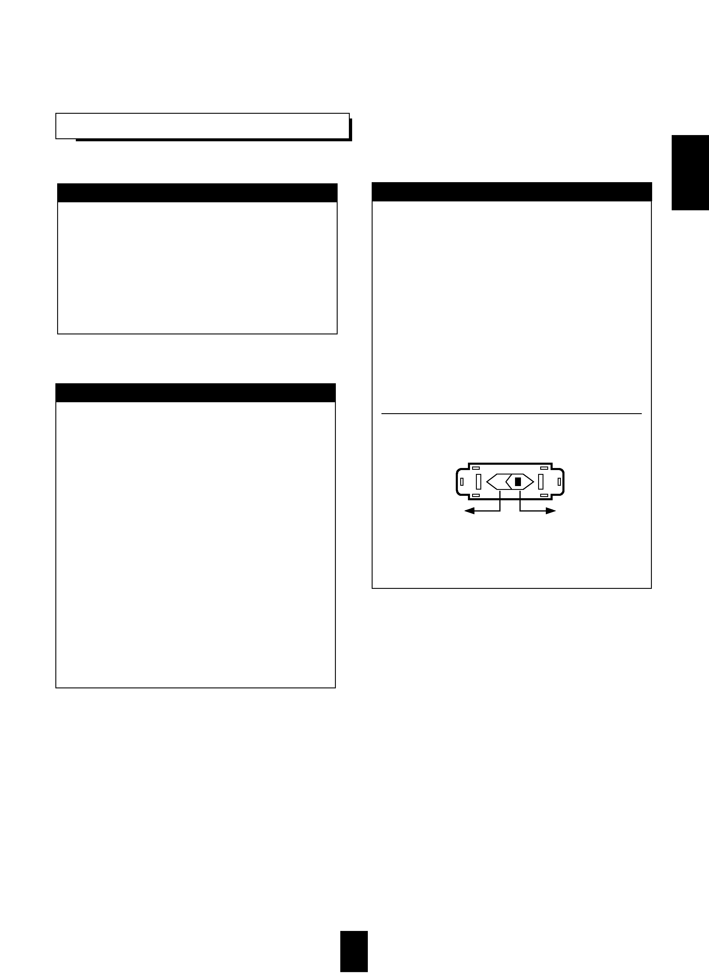
To maintain proper ventilation, be sure
to leave a space around the unit (from
the largest outer dimensions including projections)
equal to, or greater than, shown below.
Left and right panels: 5 cm
Rear panel: 10 cm
Top panel: 20 cm
EE
NN
GG
LL
IISS
HH