PIONEER XW-PSS02-S/WYXJ5 Service Manual

Cover page of PIONEER XW-PSS02-S/WYXJ5 Service Manual

Service Manual for PIONEER XW-PSS02-S/WYXJ5, downloadable as a PDF file.

We also have owner's manual to this model.

Manual details

  • Immediate download after payment.
  • Delivered as a PDF file.
  • The manual has 77 pages
  • File size: 6.38 MB
  • Available language versions: English
  • Different language versions may vary sligthly in file size and page count.

We guarantee that...

  • our manuals are complete,
  • the manual includes circuit diagrams,
  • our manuals are checked with antivirus,
  • We'll issue refund if the manual is damaged, incomplete or unreadable (our refund policy)

Sample pages

Thumbnail of page 1Thumbnail of page 2Thumbnail of page 3Thumbnail of page 4
Thumbnail of page 5Thumbnail of page 6Thumbnail of page 7Thumbnail of page 8
Thumbnail of page 9
background image
ORDER NO.
PIONEER CORPORATION 4-1, Meguro 1-chome, Meguro-ku, Tokyo 153-8654, Japan
PIONEER ELECTRONICS (USA) INC. P.O. Box 1760, Long Beach, CA 90801-1760, U.S.A.
PIONEER EUROPE NV Haven 1087, Keetberglaan 1, 9120 Melsele, Belgium
PIONEER ELECTRONICS ASIACENTRE PTE. LTD. 253 Alexandra Road, #04-01, Singapore 159936
PIONEER CORPORATION 2007
CH
Sel.
/Sensor
CH Select
Power Line Sound Station
XW-PSS01-L
XW-PSS02-S
(optional)
Standb
y /On
InputS
electo
r
Enter
Cance
l
Dual
Soun
d
Timer
RDM
Play
USB
Contro
l
XW-PSS01
RRV3512
POWER LINE SOUND SYSTEM
XW-PSS01
XW-PSS01-L
XW-PSS02-S
THIS MANUAL IS APPLICABLE TO THE FOLLOWING MODEL(S) AND TYPE(S).
XW-PSS01 is combination of the following components.
· Ask user to bring the Power Line Sound Station and Power Line Network Speaker pair
set together when servicing.
Model
Type
Power Requirement
Remarks
XW-PSS01
WYXJ5
AC 220 V to 240 V
XW-PSS01
WVXJ5
AC 220 V to 240 V
XW-PSS01-L
WYXJ5
AC 220 V to 240 V
XW-PSS01-L
WVXJ5
AC 220 V to 240 V
XW-PSS02-S
WYXJ5
AC 220 V to 240 V
XW-PSS02-S
WVXJ5
AC 220 V to 240 V
Component
System
Service Manual
Remarks
POWER LINE SOUND SYSTEM
XW-PSS01
RRV3512
POWER LINE SOUND STATION
­­­­­
RRV3512
POWER LINE NETWORK SPEAKER
­­­­­
RRV3512
POWER LINE NETWORK SPEAKER
XW-PSS01-L
RRV3512
(optional)
POWER LINE NETWORK SPEAKER
XW-PSS02-S
RRV3512
(optional)
For details, refer to "Important Check Points for Good Servicing".
T-ZZK FEB. 2007 printed in Japan
background image
XW-PSS01
2
12
34
12
3
4
C
D
F
A
B
E
SAFETY INFORMATION
background image
XW-PSS01
3
56
78
56
7
8
C
D
F
A
B
E
[Important Check Points for Good Servicing]
In this manual, procedures that must be performed during repairs are marked with the below symbol.
Please be sure to confirm and follow these procedures.
1. Product safety
Please conform to product regulations (such as safety and radiation regulations), and maintain a safe servicing environment by
following the safety instructions described in this manual.
1 Use specified parts for repair.
Use genuine parts. Be sure to use important parts for safety.
2 Do not perform modifications without proper instructions.
Please follow the specified safety methods when modification(addition/change of parts) is required due to interferences such as
radio/TV interference and foreign noise.
3 Make sure the soldering of repaired locations is properly performed.
When you solder while repairing, please be sure that there are no cold solder and other debris.
Soldering should be finished with the proper quantity. (Refer to the example)
4 Make sure the screws are tightly fastened.
Please be sure that all screws are fastened, and that there are no loose screws.
5 Make sure each connectors are correctly inserted.
Please be sure that all connectors are inserted, and that there are no imperfect insertion.
6 Make sure the wiring cables are set to their original state.
Please replace the wiring and cables to the original state after repairs.
In addition, be sure that there are no pinched wires, etc.
7 Make sure screws and soldering scraps do not remain inside the product.
Please check that neither solder debris nor screws remain inside the product.
8 There should be no semi-broken wires, scratches, melting, etc. on the coating of the power cord.
Damaged power cords may lead to fire accidents, so please be sure that there are no damages.
If you find a damaged power cord, please exchange it with a suitable one.
9 There should be no spark traces or similar marks on the power plug.
When spark traces or similar marks are found on the power supply plug, please check the connection and advise on secure
connections and suitable usage. Please exchange the power cord if necessary.
0 Safe environment should be secured during servicing.
When you perform repairs, please pay attention to static electricity, furniture, household articles, etc. in order to prevent injuries.
Please pay attention to your surroundings and repair safely.
2. Adjustments
To keep the original performance of the products, optimum adjustments and confirmation of characteristics within specification.
Adjustments should be performed in accordance with the procedures/instructions described in this manual.
4. Cleaning
For parts that require cleaning, such as optical pickups, tape deck heads, lenses and mirrors used in projection monitors, proper
cleaning should be performed to restore their performances.
3. Lubricants, Glues, and Replacement parts
Use grease and adhesives that are equal to the specified substance.
Make sure the proper amount is applied.
5. Shipping mode and Shipping screws
To protect products from damages or failures during transit, the shipping mode should be set or the shipping screws should be
installed before shipment. Please be sure to follow this method especially if it is specified in this manual.
background image
XW-PSS01
4
12
34
12
3
4
C
D
F
A
B
E
CONTENTS
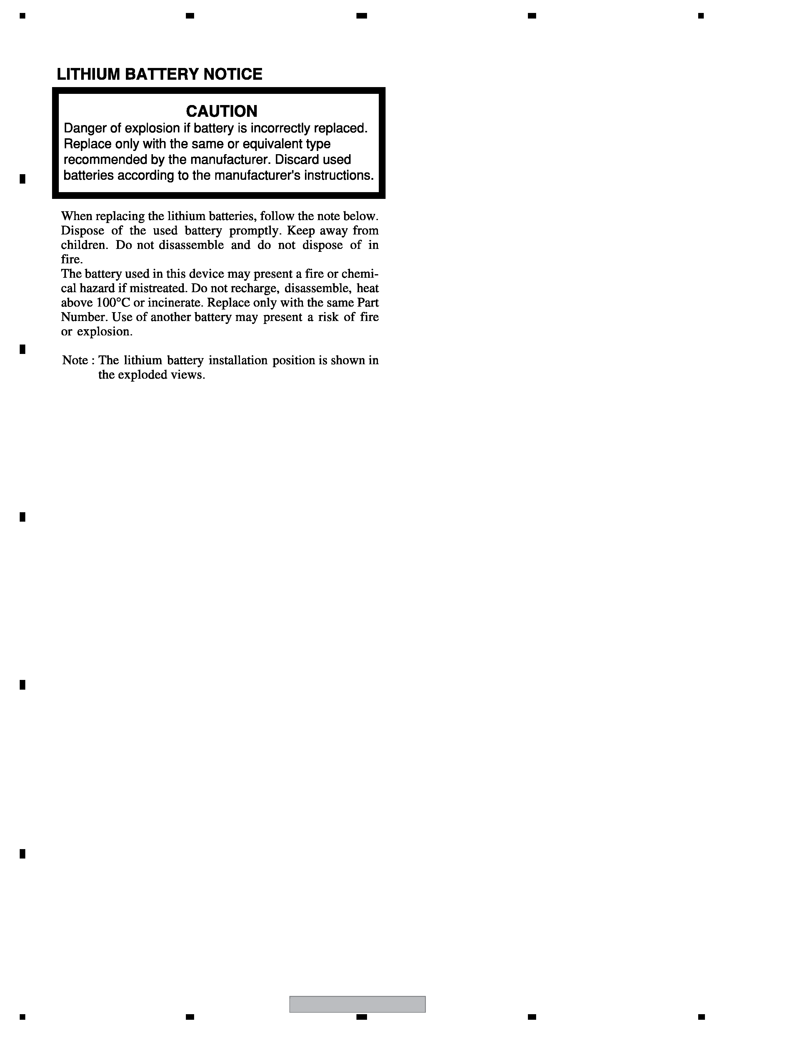
SAFETY INFORMATION ..................................................................................................................................... 2
1. SPECIFICATIONS ............................................................................................................................................ 5
2. EXPLODED VIEWS AND PARTS LIST ............................................................................................................ 6
2.1 PACKING (XW-PSS01) .............................................................................................................................. 6
2.2 PACKING (XW-PSS01-L)........................................................................................................................... 8
2.3 PACKING (XW-PSS02-S) ........................................................................................................................ 10
2.4 SELECTOR ASSY ................................................................................................................................... 12
2.5 SPEAKER L ASSY .................................................................................................................................. 14
2.6 SPEAKER S ASSY .................................................................................................................................. 16
3. BLOCK DIAGRAM AND SCHEMATIC DIAGRAM ..........................................................................................18
3.1 POWER LINE SOUND STATION BLOCK DIAGRAM .............................................................................. 18
3.2 POWER LINE NETWORK SPEAKER BLOCK DIAGRAM ...................................................................... 20
3.3 OVERALL WIRING CONNECTION DIAGRAM........................................................................................ 22
3.4 AUDIO (1/2) and BOARD TO BOARD ASSYS ........................................................................................24
3.5 AUDIO (2/2), DISPLAY KEY and FRONT INPUT ASSYS ....................................................................... 26
3.6 USB ASSY ............................................................................................................................................... 28
3.7 MAIN L ASSY .......................................................................................................................................... 30
3.8 DISPLAY & KEY and REMOCON ASSYS ............................................................................................... 32
3.9 MAIN S, KEY, MOTION and AMP ASSYS ............................................................................................... 34
4. PCB CONNECTION DIAGRAM ..................................................................................................................... 36
4.1 DISPLAY KEY ASSY ............................................................................................................................... 37
4.2 AUDIO, BOARD TO BOARD and FRONT INPUT ASSYS....................................................................... 38
4.3 USB ASSY ............................................................................................................................................... 40
4.4 MAIN L ASSY .......................................................................................................................................... 41
4.5 MAIN S, KEY, MOTION SENSOR and AMP ASSYS............................................................................... 42
4.6 DISPLAY & KEY and REMOCON ASSYS ............................................................................................... 44
5. PCB PARTS LIST ........................................................................................................................................... 45
6. ADJUSTMENT ............................................................................................................................................... 53
7. GENERAL INFORMATION ............................................................................................................................. 54
7.1 DIAGNOSIS ............................................................................................................................................. 54
7.1.1 SERVICE TESTMODE ...................................................................................................................... 54
7.1.2 ID REGISTRATION............................................................................................................................ 56
7.1.3 PROTECTION AND ABNORMAL CONDITION DETECTION........................................................... 57
7.1.4 POWER ON SEQUENCE.................................................................................................................. 58
7.1.5 POWER LINE SOUND SYSTEM CONNECTIONS........................................................................... 59
7.1.6 TROUBLESHOOTING ....................................................................................................................... 60
7.1.7 DISASSEMBLY.................................................................................................................................. 61
7.2 IC ............................................................................................................................................................. 71
8. PANEL FACILITIES ........................................................................................................................................ 77
background image
XW-PSS01
5
56
78
56
7
8
C
D
F
A
B
E
1. SPECIFICATIONS
Standby/On
Input Sel.
USB Control
Sound
Mute
Lithium battery
(CR2025)
· Remote control unit (XZN3188)
· AC Power Cord
(WYXJ5 : XDG3024)
(WVXJ5 : XDG3026)
Power Line Sound Station
Power consumption..................................................................................................................................8 W
In standby.............................................................................................................................................6 W
Power Requirements
European/UK models...............................................................................AC 230 V to 240 V, 50 Hz/60 Hz
Dimensions......................................................................................250 (W) mm x 47 (H) mm x 183 (D) mm
Weight....................................................................................................................................................1.2 kg
XW-PSS01-L
Power consumption................................................................................................................................24 W
..In standby...........................................................................................................................................6 W
Power output...............................................................................................................25 W/ch (1 kHz, 10 %)
Power Requirements
European/UK models...............................................................................AC 230 V to 240 V, 50 Hz/60 Hz
Enclosure........................................................................Closed-box bookshelf type (magnetically shielded)
Configuration
Full-range............................................................................................................................7.7 cm cone x 2
Nominal impedance.......................................................................................................................................6
Dimensions....................................................................................452 (W) mm x 162 (H) mm x 112 (D) mm
Weight...................................................................................................................................................2.8 kg
XW-PSS02-S (Optional)
Power consumption..................................................................................................................................7 W
In standby..............................................................................................................................................4 W
Power output......................................................................................................................5 W (1 kHz, 10 %)
Power Requirements
European/UK models...............................................................................AC 230 V to 240 V, 50 Hz/60 Hz
Enclosure........................................................................Closed-box bookshelf type (magnetically shielded)
Configuration
Full-range..................................................................................................................................5.2 cm cone
Nominal impedance.......................................................................................................................................8
Dimensions....................................................................................109 (W) mm x 176 (H) mm x 109 (D) mm
Weight...................................................................................................................................................1.2 kg
Accessories
Remote control..............................................................................................................................................1
Power cord....................................................................................................................................................1
Lithium battery (CR2025)..............................................................................................................................1
Operating instructions

Reviews

There are no reviews of this manual yet.