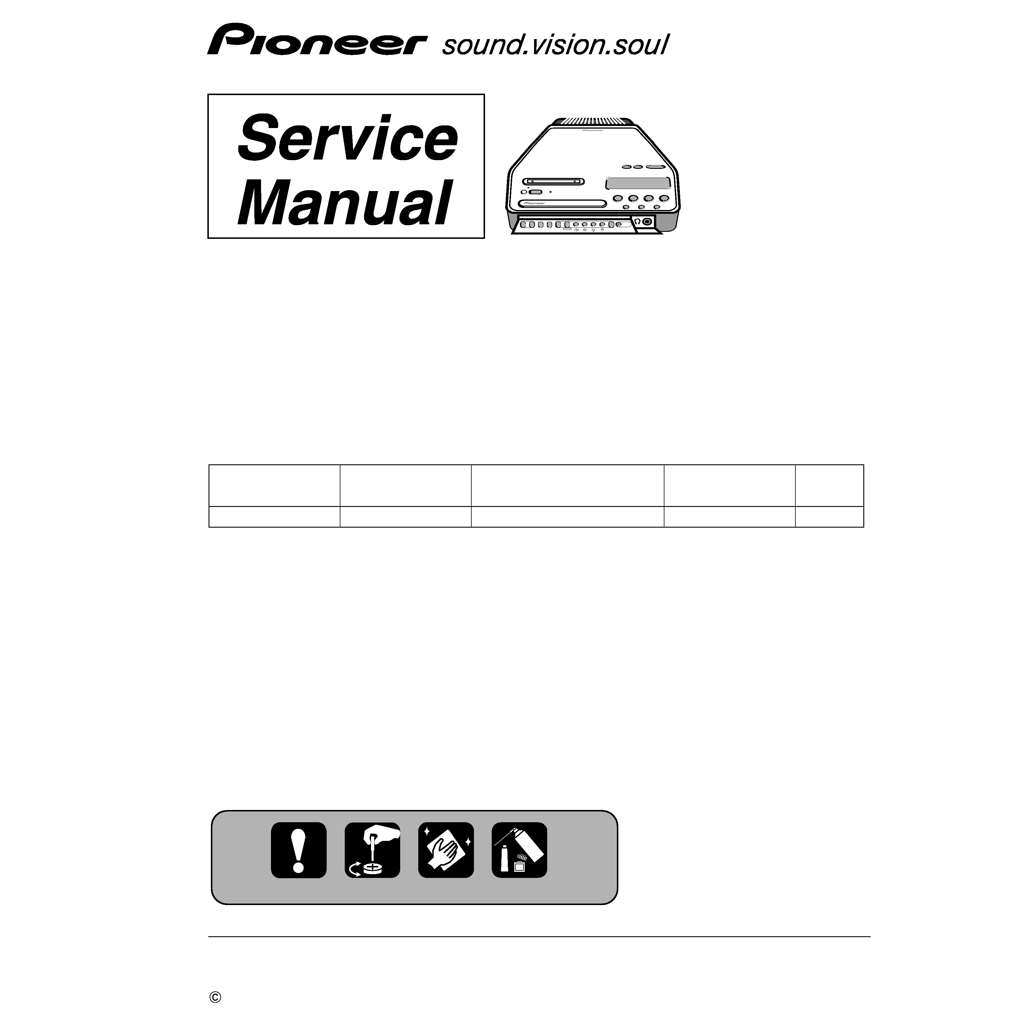
PIONEER XV-PR7DV/NXCN/HK Service Manual

Cover page of PIONEER XV-PR7DV/NXCN/HK Service Manual

Service Manual for PIONEER XV-PR7DV/NXCN/HK, downloadable as a PDF file.

We also have owner's manual to this model.

Manual details

  • Immediate download after payment.
  • Delivered as a PDF file.
  • The manual has 167 pages
  • File size: 14.54 MB
  • Available language versions: English
  • Different language versions may vary sligthly in file size and page count.

We guarantee that...

  • our manuals are complete,
  • the manual includes circuit diagrams,
  • our manuals are checked with antivirus,
  • We'll issue refund if the manual is damaged, incomplete or unreadable (our refund policy)

Sample pages

Thumbnail of page 1Thumbnail of page 2Thumbnail of page 3Thumbnail of page 4
Thumbnail of page 5Thumbnail of page 6Thumbnail of page 7Thumbnail of page 8
Thumbnail of page 9
background image
ORDER NO.
PIONEER CORPORATION 4-1, Meguro 1-chome, Meguro-ku, Tokyo 153-8654, Japan
PIONEER ELECTRONICS (USA) INC. P.O. Box 1760, Long Beach, CA 90801-1760, U.S.A.
PIONEER EUROPE NV Haven 1087, Keetberglaan 1, 9120 Melsele, Belgium
PIONEER ELECTRONICS ASIACENTRE PTE. LTD. 253 Alexandra Road, #04-01, Singapore 159936
PIONEER CORPORATION 2003
DVD/CD
0
MD
0
­ VOLUME +
DVD/CD
6
TIMER
DIRECT
REC
DIRECT
X2REC
REC/
STOP
DISP/
CHARA
ENTER
COLOR
SELECTOR
MD MENU/
SET UP
CLEAR
CD
I
MD
MD
6
74 ÷ 1
¡ ÷ ¢
FM/AM
LINE1/2
STANDBY/ON
XV-PR7DV
RRV2774
DVD/MD RECEIVER
XV-PR7DV
THIS MANUAL IS APPLICABLE TO THE FOLLOWING MODEL(S) AND TYPE(S).
Model
Type
Power Requirement
Reginal restriction
codes (Region No.)
Remarks
XV-PR7DV
NXCN/HK
AC220V
3
For details, refer to "Important symbols for good services" .
T-ZZR 2003.06 2003 printed in Japan
background image
XV-PR7DV
2
1234
123
4
C
D
F
A
B
E
SAFETY INFORMATION
This service manual is intended for qualified service technicians ; it is not meant for the casual do-
it-yourselfer. Qualified technicians have the necessary test equipment and tools, and have been
trainedto properly and safely repair complex products such as those covered by this
manual.Improperly performed repairs can adversely affect the safety and reliability of the product
and mayvoid the warranty. If you are not qualified to perform the repair of this product properly and
safely, youshould not risk trying to do so and refer the repair to a qualified service technician.
WARNING !
THE AEL (ACCESSIBLE EMISSION LEVEL) OF THE LASER POWER OUTPUT IS LESS THAN CLASS 1
BUT THE LASER COMPONENT IS CAPABLE OF EMITTING RADIATION EXCEEDING THE LIMIT FOR
CLASS 1.
A SPECIALLY INSTRUCTED PERSON SHOULD DO SERVICING OPERATION OF THE APPARATUS.
LASER DIODE CHARACTERISTICS
FOR DVD : MAXIMUM OUTPUT POWER : 5 mW
WAVELENGTH : 650 nm
FOR CD :
MAXIMUM OUTPUT POWER : 7 mW
WAVELENGTH : 780 nm
LASER DIODE CHARACTERISTICS
FOR MD : MAXIMUM OUTPUT POWER : 41mW
WAVELENGTH: 780 - 800 nm
Additional Laser Caution
for DVD
: See page 79.
1. Laser Interlock Mechanism
· Loading switch (S101 on the LOAB Assy) is used for interlock
mechanism of the laser.
When this switch turned ON in SW2 (XCLOSE) side (OPEN signal is
0V and XCLOSE signal is 3.5V), a laser becomes the status which
can completely oscillate.
Furthermore, the laser completely oscillates in the disc judgment and
disc playback.
When player is power ON state and laser diode is not completely
oscillating, 780nm laser diode is always oscillating by half power.
· Laser diode is driving with Q101 (650nm LD) and Q102 (780nm LD)
on the DVDM Assy.
Therefore, when short-circuit between the emitter and collector of
these transistors or the base voltage is supplied for transistors turn
on, the laser oscillates. (failure mode)
· In the test mode
, there is the mode that the laser oscillates except
for the disc judgment and playback. LD ON mode in the test mode
oscillates with the laser forcibly.
The interlock mechanism mentioned above becomes invalid in this
mode.
2. When the cover is open, close viewing through the objective lens with
the naked eye will cause exposure to the laser beam.
Additional Laser Caution
for MD
Control method of the current through a laser diode.
The resistor R166 on the MD MOUNT ASSY (For MD mechanism
assembly) are for the limiting of current through a laser diode.
Control method of the laser output power
The laser pick-up assembly provide the photo-diodes and APC (Auto
Power Control) circuit.
The photo-diode detect output of the laser diode then IC201 control the
APC circuit according to the signal voltage of the photo-diode via IC101.
Laser Interlock Switch
The loading position detect switch is set to " LOAD ON " position, IC201
get the " LOAD " signal, and hand the laser " LDON " signal to APC (Auto
Power Control) circuit of the Laser pick-up assembly.
Then a laser diode can be lighted when the " LOAD " signal is " LOAD
ON " position.
VRW1872
LABEL CHECK
background image
XV-PR7DV
3
5
678
56
7
8
C
D
F
A
B
E
[ Important symbols for good services ]
In this manual, the symbols shown-below indicate that adjustments, settings or cleaning should be made securely.
When you find the procedures bearing any of the symbols, be sure to fulfill them:
2. Adjustments
To keep the original performances of the product, optimum adjustments or specification confirmation is indispensable.
In accordance with the procedures or instructions described in this manual, adjustments should be performed.
3. Cleaning
For optical pickups, tape-deck heads, lenses and mirrors used in projection monitors, and other parts requiring cleaning,
proper cleaning should be performed to restore their performances.
5. Lubricants, glues, and replacement parts
Appropriately applying grease or glue can maintain the product performances. But improper lubrication or applying
glue may lead to failures or troubles in the product. By following the instructions in this manual, be sure to apply the
prescribed grease or glue to proper portions by the appropriate amount.For replacement parts or tools, the prescribed
ones should be used.
4. Shipping mode and shipping screws
To protect the product from damages or failures that may be caused during transit, the shipping mode should be set or
the shipping screws should be installed before shipping out in accordance with this manual, if necessary.
1. Product safety
You should conform to the regulations governing the product (safety, radio and noise, and other regulations), and
should keep the safety during servicing by following the safety instructions described in this manual.
DVD-Video
MiniDisc
MiniDisc Long Play
Video CD
Super Video CD (Super VCD)
Audio CD
CD-R
CD-RW
DVD-R
DVD-RW
Disc / content format
playback compatibility
General disc compatibility
This player was designed and engineered to
be compatible with software bearing one or
more of the following logos:
· KODAK Picture CD
·
is a trademark of Fuji Photo Film Co.
Ltd.
This player supports the IEC's Super VCD
standard. Compared to the Video CD stan-
dard, Super VCD offers superior picture
quality, and allows two stereo soundtracks to
be recorded. Super VCD also supports the
widescreen size.
Other formats, including but not limited to the
following, are not playable in this player:
DVD-Audio / SACD / DVD-RAM
DVD-ROM / CD-ROM*
DVD-R/RW and CD-R/RW discs (Audio CDs
and Video CD/Super VCDs) recorded using a
DVD recorder, CD recorder or personal
computer may not be playable on this unit.
This may be caused by a number of possibili-
ties, including but not limited to: the type of
disc used; the type of recording; damage, dirt
or condensation on either the disc or the
player's pick-up lens. See Disc Compatibility
on page 9 for notes about particular software
and formats.
Disc Compatibility
CD-R/RW compatibility
· This unit will play CD-R and CD-RW discs
recorded in CD Audio or Video CD/Super
VCD format, or as a CD-ROM containing
WMA, MP3 or JPEG files. However, any
other content may cause the disc not to
play, or create noise/distortion in the
output.
· This unit cannot record CD-R or CD-RW
discs.
· Unfinalized CD-R/RW discs recorded as
CD Audio can be played, but the full Table
of Contents (playing time, etc.) will not be
displayed.
DVD-R/RW compatibility
· This unit will play DVD-R/RW discs
recorded using the DVD-Video format that
have been finalized using a DVD-recorder.
· This unit will play DVD-RW discs recorded
using the Video Recording (VR) format.
· DVD-RW shows in the display when a VR
format DVD-RW disc is loading.
Fujicolor CD
background image
XV-PR7DV
4
1234
123
4
C
D
F
A
B
E
CONTENTS
SAFETY INFORMATION ..................................................................................................................................... 2
1. SPECIFICATIONS ............................................................................................................................................ 5
2. EXPLODED VIEWS AND PARTS LIST ............................................................................................................ 6
2.1 PACKING SECTION .................................................................................................................................. 7
2.2 EXTERIOR SECTION (1/2) ....................................................................................................................... 8
2.3 EXTERIOR SECTION (2/2) ..................................................................................................................... 10
2.4 FRONT PANEL SECTION ....................................................................................................................... 12
2.5 AMP MODULE SECTION ........................................................................................................................ 14
2.6 LOADING MECHA. ASSY ....................................................................................................................... 16
2.7 OEL POSITION........................................................................................................................................ 17
2.8 TRAVERSE MECHA. ASSY-S ................................................................................................................. 18
2.9 MD MECHA. (1/2 : LOADING ASSY) ...................................................................................................... 20
2.10 MD MECHA. (2/2 : MECHA. DECK ASSY) ............................................................................................ 22
3. BLOCK DIAGRAM AND SCHEMATIC DIAGRAM ..........................................................................................24
3.1 OVERALL BLOCK DIAGRAM.................................................................................................................. 24
3.2 DVD SECTION BLOCK DIAGAM ............................................................................................................ 26
3.3 LOAB ASSY and OVERALL WIRING DIAGAM ....................................................................................... 28
3.4 DVDM ASSY (1/3).................................................................................................................................... 30
3.5 DVDM ASSY (2/3).................................................................................................................................... 32
3.6 DVDM ASSY (3/3).................................................................................................................................... 34
3.7 FM/AM TUNER MODULE ........................................................................................................................ 36
3.8 MD MOUNT ............................................................................................................................................. 38
3.9 DVD CONNECTION and CONTROL (1/3) ASSYS.................................................................................. 40
3.10 CONTROL(2/3), WHITE LED and FUNCTION LED ASSYS ................................................................. 42
3.11 CONTROL ASSY (3/3)........................................................................................................................... 44
3.12 REGULATOR and AMP ASSYS ............................................................................................................ 46
3.13 SIDE, HP, SECONDARY and PRIMARY ASSYS................................................................................... 48
3.14 TOP KEY, SW, REMOCON and LCD ASSYS........................................................................................ 50
4. PCB CONNECTION DIAGRAM ..................................................................................................................... 52
4.1
.......................................................................................................................................... 52
4.2 DVDM ASSY ............................................................................................................................................ 53
4.3 FM/AM TUNER MODULE ........................................................................................................................ 55
4.4 MD MOUNT ............................................................................................................................................. 56
4.5 WHITE LED and FUNCTION LED ASSY ................................................................................................ 58
4.6 REGULATOR and AMP ASSY ................................................................................................................. 60
4.7 CONTROL and DVD CONNCTION ASSY............................................................................................... 62
4.8 SIDE and HP ASSYS............................................................................................................................... 66
4.9 SECONDARY, TOP KEY and SW ASSYS ............................................................................................... 68
4.10 PRIMARY ASSYS .................................................................................................................................. 70
4.11 LCD and REMOCON ASSYS ................................................................................................................ 71
5. PCB PARTS LIST ........................................................................................................................................... 72
6. ADJUSTMENT ............................................................................................................................................... 79
6.1 DVD SECTION......................................................................................................................................... 79
6.1.1 ADJUTMENT ITEMS AND LACATION ..............................................................................................79
6.1.2 JIGS AND MEASURING INSTRUMENTS ........................................................................................ 79
6.1.3 NECESSARY ADJUSTMENT POINTS ............................................................................................. 80
6.1.4 TEST MODE ...................................................................................................................................... 81
6.1.5 MECHANISM ADJUSTMENT............................................................................................................ 82
6.2 TUNER SECTION .................................................................................................................................... 84
6.3 MD SECTION........................................................................................................................................... 85
7. GENERAL INFORMATION ............................................................................................................................. 98
7.1 DIAGNOSIS ............................................................................................................................................. 98
7.1.1 DVD TEST MODE.............................................................................................................................. 98
7.1.2 DVD MECHANICAL ERROR HISTORY .......................................................................................... 103
7.1.3 ID NUMBER AND ID DATA SETTING ............................................................................................. 106
7.1.4 Sequences After the Power is Turned ON/OFF ............................................................................... 109
7.1.5 Specifications of the PROTECT / DETECT of the System Controller.............................................. 113
7.1.6 DVD Troubleshooting ....................................................................................................................... 115
7.1.7 MD Troubleshooting ......................................................................................................................... 117
7.1.8 DVD TEST POINT LOCATION & WAVEFORMS ............................................................................. 122
7.1.9 DISASSEMBLY................................................................................................................................ 124
7.2 PARTS.................................................................................................................................................... 140
7.2.1 IC ..................................................................................................................................................... 140
7.2.2 DISPLAY .......................................................................................................................................... 156
7.3 CIRCUIT DESCRIPTION ....................................................................................................................... 157
7.4 CLEANING............................................................................................................................................. 161
8. PANEL FACILITIES ...................................................................................................................................... 162
background image
XV-PR7DV
5
5
678
56
7
8
C
D
F
A
B
E
1. SPECIFICATIONS
Amplifier Section
Continuous Power (RMS) ............................................. 25 W + 25 W
(1 kHz, THD 10%, 4
)
Disc section
Digital audio
characteristics ................................................ DVD fs: 96kHz, 24-bit
Type ......................................... DVD system, Video CD system and
Compact Disc digital audio system
Frequency response ................................................. 4 Hz to 44 kHz
(DVD fs: 96 kHz)
MiniDisc section
Recording method ...................................................... Magnetic-field
modulation overwrite type
Playback method ............................................... Non-contact optical
Sampling frequency ............................................................ 44.1kHz
FM tuner section
Frequency Range ..................................................... 87.5 ­ 108MHz
Antenna ................................................................ 75
, unbalanced
AM tuner section
FrequencyRange
With 9 kHz step ........................................... 531kHz to 1,602kHz
With 10 kHz step ......................................... 530kHz to 1,700kHz
Antenna ...................................................................... Loop antenna
Miscellaneous
Power Requirements ................................................ AC 220V, 50Hz
Power Consumption ............................................................... 207 W
Power Consumption in standby mode ................................... 0.07 W
Dimensions:
DVD Tuner Deck ......................... 245 (W) x 112.5 (H) x 368 (D) mm
Weight .................................................................................... 6.0 kg
Accessories
Accessories
Operating instructions .................................................................... 1
Remote control .............................................................................. 1
Dry cell batteries (AA/R6) .............................................................. 2
Power cord ..................................................................................... 1
Video cord ...................................................................................... 1
FM antenna ................................................................................... 1
AM loop antenna ............................................................................ 1
Speaker System S-PR7-S-LR
Enclosure ............................................... Bass-reflex bookshelf type
(magnetically shielded)
System ....................................................................... 2-way system
Speakers:
Woofer .......................................................... 10x7 cm cone type
Tweeter .......................................................... 20 mm dome type
Nominal impedance ................................................................... 4
Frequency range ..................................................... 55 Hz to 20 kHz
Maximum power ....................................................................... 25 W
Dimensions ................................... 98 (W) x 220 (H) x 275 (D) mm
Weight .................................................................................... 1.7 kg
· Specifications and design subject to possible modification
without notice, due to improvements.
· Remote control
· AA/R6P dry cell batteries x2
· FM wire antenna
· AM loop antenna
· Video cord
·Power cable
* Manufactured under license from Dolby Laboratories. "Dolby"
and the double-D symbol are trademarks of Dolby Laboratories.
* "DTS" is a registered trademark of Digital Theater Systems,
Inc.
*TruSurround, SDS and
®
symbol are trademarks of SRS
Labs, Inc. TruSurround technology is incorporated under
license from SRS Labs, Inc.
(064-10001-005)
(043-26152-511)
YELLOW
(015-80004-001)
(AXD7360)
(023-60060-114)
MD
5
4
6
8
79
0
2
13
TOP MENU
DVD MENU
RETURN
TUNE
TUNE
ST
ST
ENTER
HOME
MENU
VOLUME
DVD
/CD
STANDBY
/ON
MD
FM
/AM
LINE
(L1/L2)
MUTE
SURR
SOUND
SFC
PGM
REPEAT
RANDOM
/ SETUP
ZOOM
BGM MODE
SUBTITLE
ANGLE
AUDIO
DVD
MD MENU
DVD/CD
MD
REC THIS
FOLDER / GROUP
MD
DISP/
CHARA
TIMER /
CLOCK
GHI
JKL
MNO
PQRS
TUV
WXYZ
MARK
ENTER
CLEAR
ABC
DEF
Speaker wire
............................................................................ 2

Reviews

There are no reviews of this manual yet.