XV-HTD7
5
5
678
56
7
8
C
D
F
A
B
E
1. SPECIFICATIONS
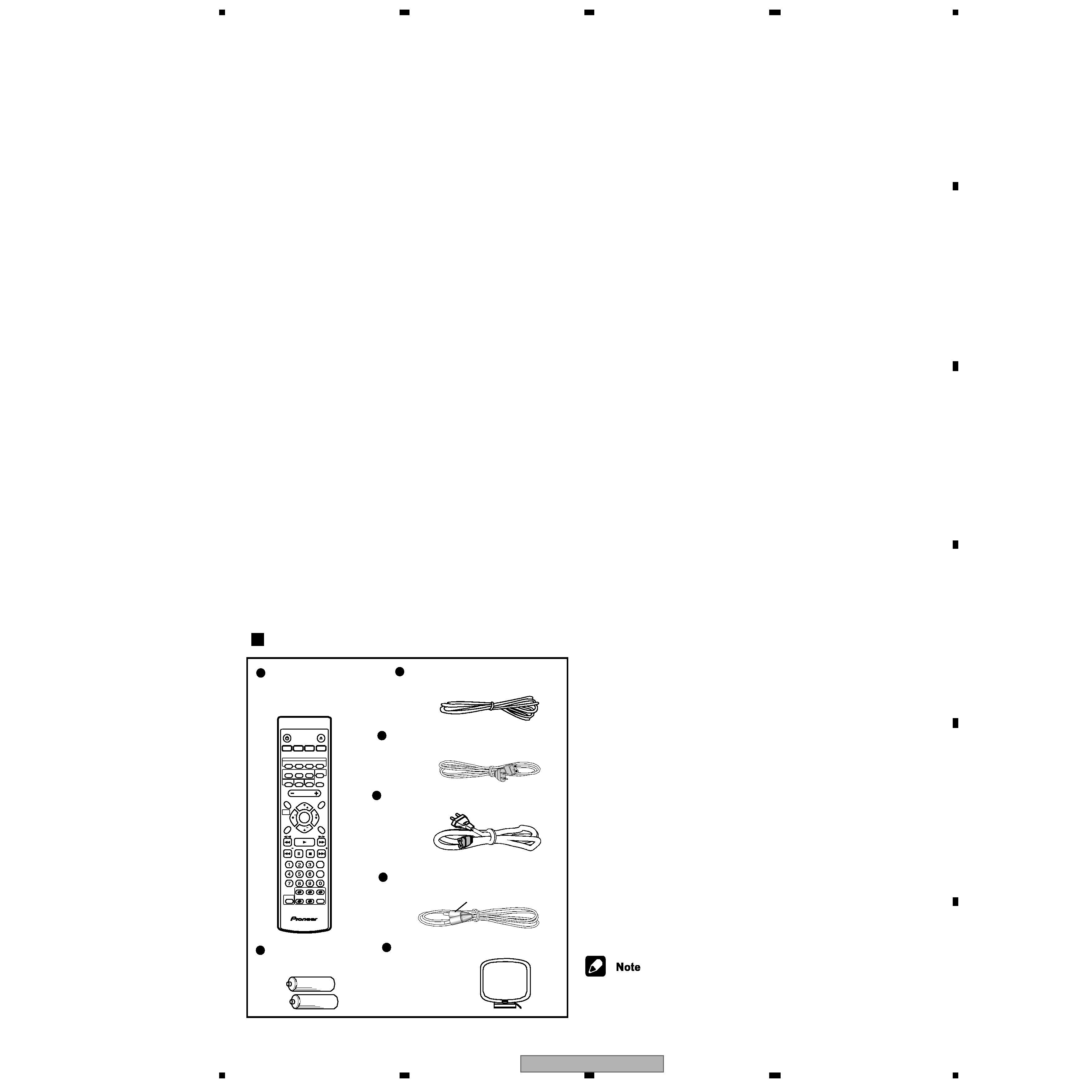
Accessories
Remote Control Unit
x 1 (AXD7353)
FM Antenna
x 1
(ADH7004)
AM Loop Antenna
x 1
(ATB7009)
AA/R6P Dry Cell
Batteries
x 2
Power Cord
x 1
(ADG1158)
Video Cord
x 1
(VDE1065)
Yellow (L=1.5m)
Power Cord
x 1
(ADG1160)
OPEN/CLOSE
STANDBY/ON
L1/L2
FM/AM
AUDIO SUBTITLE ANGLE
ZOOM
AUTO
FOLDER
MUTE
SURROUND
SYSTEM SETUP
HOME
MENU
TOP MENU
DVD MENU
SOUND
MODE
RETURN
SHIFT
QUIET/
MIDNIGHT
ADVANCED
ROOM
SETUP
BASS MODE
VIR.SB
DIALOGUE
ST
TUNE
VOLUME
ST
TUNE
DVD/CD
CLEAR
ENTER
ENTER
TUNER
TV
LINE
DVD
FOLDER
PROGRAM REPEAT RANDOM
TEST TONE CH LEVEL
TIMER
DISPLAY
DISC 1
DISC 2
DISC 3
DISC 4
SURROUND
5.1ch DVD
SYSTEM
DISC 5
CD MODE
DISC SKIP
DIMMER
Specifications
Amplifier section
Continuous Power Output (RMS):
Front, center, surround. . . . .100 W per channel
(1 kHz, 10 % T.H.D., 6
)
Subwoofer . . .100 W (100 Hz, 10 % T.H.D., 6
)
Disc section
Digital audio
characteristics . . . . . . . .DVD fs: 96 kHz, 24-bit
Type. . . . . . .DVD system, video CD system and
compact disc digital audio system
Frequency response. . . . . . . . . .4 Hz to 44 kHz
Wow and Flutter. . . . . . . .Limit of measurement
(
±0.001 % W.PEAK) or less (JEITA)
FM tuner section
Frequency range . . . . . . . . . . . . .
87.5 108 MHz
Antenna . . . . . . . . . . . . . . . . .75
, unbalanced
AM tuner section
Frequency range
With 9 kHz step . . . . . . . . .531 kHz to 1,602 kHz
With 10 kHz step . . . . . . . .530 kHz to 1,700 kHz
(Except for Saudi Arabia model)
Antenna . . . . . . . . . . . . . . . . . . . . .
Loop antenna
Miscellaneous
Power requirements
. . . . . . AC 120-127V / 220-230V / 240V / 50/60Hz
Power consumption . . . . . . . . . . . . . . . . .180 W
Power consumption in standby
. . . . . . . . . . . . . . . . . . . . . . . .
0.40 W (120V/ 60Hz)
. . . . . . . . . . . . . . . . . . . . .
0.58 W (127V/ 50/60Hz)
Dimensions . . . 420 (W) x 125 (H) x 448 (D) mm
Weight . . . . . . . . . . . . . . . . . . . . . . . . . . . . .
9.8 kg
Accessories (DVD/CD receiver)
Remote control . . . . . . . . . . . . . . . . . . . . . . . . . . 1
AA/R6P dry cell batteries. . . . . . . . . . . . . . . . . . 2
Video cable (yellow plugs). . . . . . . . . . . . . . . . . 1
AM loop antenna . . . . . . . . . . . . . . . . . . . . . . . . 1
FM antenna . . . . . . . . . . . . . . . . . . . . . . . . . . . .1
Power cable. . . . . . . . . . . . . . . . . . . . . . . . . . . . .1
(Central and South American model x2)
Power plug adapter . . . . . . . . . . . . . . . . . . . . . .1
(
Central and South American model, PX
model and Duty-free model within Japan only)
Warranty card . . . . . . . . . . . . . . . . . . . . . . . . . .1
(Australian and New Zealand model only)
Operating instructions
Speaker System
Front speakers
Enclosure . . . . . . . . .Closed-box bookshelf type
(magnetically shielded)
System. . . . . . . . . . . . . . . . . . . . . . .2-way system
Speakers
Woofer . . . . . . . . . . . . . . . . . 10 cm cone type
Tweeter . . . . . . . . . . . . . . . . .5.2 cm cone type
Nominal impedance . . . . . . . . . . . . . . . . . . . .6
Frequency range . . . . . . . . . . . .60 Hz to 20 kHz
Maximum Input Power. . . . . . . . . . . . . . . .100 W
Dimensions . . . .145 (W) x 235 (H) x 204 (D) mm
Weight . . . . . . . . . . . . . . . . . . . . . . . . . . . . . . .2 kg
Center speaker
Enclosure . . . . . . . . .Closed-box bookshelf type
(magnetically shielded)
System. . . . . . . . . . . . . . . . .8.7 cm 1-way system
Speakers . . . . . . . . . . . . . . . . . .8.7 cm cone type
Nominal impedance . . . . . . . . . . . . . . . . . . . .6
Frequency range . . . . . . . . . . . .70 Hz to 20 kHz
Maximum Input Power. . . . . . . . . . . . . . . .100 W
Dimensions . . . . .310 (W) x 110 (H) x 85 (D) mm
Weight . . . . . . . . . . . . . . . . . . . . . . . . . . . . . . .1 kg
Surround speakers
Enclosure . . . . . . . . .Closed-boxbookshelftype
(magnetically shielded)
System. . . . . . . . . . . . . . . . .
8.7 cm 1-way system
Speakers . . . . . . . . . . . . . . . . . .
8.7 cm cone type
Nominal impedance . . . . . . . . . . . . . . . . . . . .
6
Frequency range . . . . . . . . . . . .90 Hz to 20 kHz
Maximum Input Power. . . . . . . . . . . . . . . .
100 W
Dimensions . . . . .110 (W) x 155 (H) x 82 (D) mm
Weight . . . . . . . . . . . . . . . . . . . . . . . . . . . . .
0.8 kg
Subwoofer
Enclosure . . . . . . . . . . . . .Bass-reflexfloor type
System. . . . . . . . . . . . . . . . .
16 cm 1-way system
Speaker . . . . . . . . . . . . . . . . . . .
16 cm cone type
Nominal impedance . . . . . . . . . . . . . . . . . . . .
6
Frequency range . . . . . . . . . . . . .35 Hz to 2 kHz
Maximum Input Power. . . . . . . . . . . . . . . .
100 W
Dimensions . . . .190 (W) x 360 (H) x 327 (D) mm
Weight . . . . . . . . . . . . . . . . . . . . . . . . . . . . .
5.0 kg
Accessories (Speaker system)
Speaker cables. . . . . . . . . . . . . . . . . . . . . . . . . . .6
non-skid pads. . . . . . . . . . . . . . . . . . . . . . 1 sheet
· Specifications and design subject to
possible modification without notice, due
to improvements.