PIONEER XV-HTD340/KUXJ/CA Service Manual

Cover page of PIONEER XV-HTD340/KUXJ/CA Service Manual

Service Manual for PIONEER XV-HTD340/KUXJ/CA, downloadable as a PDF file.

We also have owner's manual to this model.

Manual details

  • Immediate download after payment.
  • Delivered as a PDF file.
  • The manual has 138 pages
  • File size: 19.46 MB
  • Available language versions: English
  • Different language versions may vary sligthly in file size and page count.

We guarantee that...

  • our manuals are complete,
  • the manual includes circuit diagrams,
  • our manuals are checked with antivirus,
  • We'll issue refund if the manual is damaged, incomplete or unreadable (our refund policy)

Sample pages

Thumbnail of page 1Thumbnail of page 2Thumbnail of page 3Thumbnail of page 4
Thumbnail of page 5Thumbnail of page 6Thumbnail of page 7Thumbnail of page 8
Thumbnail of page 9
background image
ORDER NO.
PIONEER CORPORATION 4-1, Meguro 1-chome, Meguro-ku, Tokyo 153-8654, Japan
PIONEER ELECTRONICS (USA) INC. P.O. Box 1760, Long Beach, CA 90801-1760, U.S.A.
PIONEER EUROPE NV Haven 1087, Keetberglaan 1, 9120 Melsele, Belgium
PIONEER ELECTRONICS ASIACENTRE PTE. LTD. 253 Alexandra Road, #04-01, Singapore 159936
PIONEER CORPORATION 2004
PHONES
STANDBY/ON
DOWN
VOLUME
CD MODE TIMER
UP
DVD/CD
TUNER
TV/L1/L2
FM/AM/ST.
DIRECT PLAY
DISC SKIP
EXCHANGE
OPEN/CLOSE
12
3
4
5
DISC
12
34
5
XV-HTD340
RRV2888
DVD/CD RECEIVER
XV-HTD340
THIS MANUAL IS APPLICABLE TO THE FOLLOWING MODEL(S) AND TYPE(S).
Model
Type
Power Requirement
Regional restriction
codes (Region No.)
Remarks
XV-HTD340
KUXJ/CA
AC120V
1
For details, refer to "Important symbols for good services".
T-ZZV MAR. 2004 printed in Japan
background image
XV-HTD340
2
1234
123
4
C
D
F
A
B
E
SAFETY INFORMATION
This service manual is intended for qualified service technicians; it is not meant for the casual
do-it-yourselfer. Qualified technicians have the necessary test equipment and tools, and have been
trained to properly and safely repair complex products such as those covered by this manual.
Improperly performed repairs can adversely affect the safety and reliability of the product and may
void the warranty. If you are not qualified to perform the repair of this product properly and safely, you
should not risk trying to do so and refer the repair to a qualified service technician.
WARNING
This product contains lead in solder and certain electrical parts contain chemicals which are known to the state of California to
cause cancer, bir th defects or other reproductive harm.
Health & Safety Code Section 25249.6 ­ Proposition 65
NOTICE
(FOR CANADIAN MODEL ONLY)
Fuse symbols
(fast operating fuse)
and/or
(slow operating fuse) on PCB indicate that replacement
parts must be of identical designation.
REMARQUE
(POUR MODÈLE CANADIEN SEULEMENT)
Les symboles de fusible
(fusible de type rapide)
et/ou
(fusible de type lent) sur CCI indiquent que
les pièces de remplacement doivent avoir la même désignation.
ANY MEASUREMENTS NOT WITHIN THE
LIMITS OUTLINED ABOVE ARE INDICATIVE
OF A POTENTIAL SHOCK HAZARD AND
MUST BE CORRECTED BEFORE RETURN-
ING THE APPLIANCE TO THE CUSTOMER.
2. PRODUCT SAFETY NOTICE
Many electrical and mechanical parts in the appliance
have special safety related character istics. These are
often not evident
from visual
inspection nor the
protection afforded by them necessarily can be obtained
by using replacement components rated for voltage,
wattage, etc. Replacement parts which have these
special safety characteristics are identified in this
Service Manual.
Electrical components having such features are
identified by marking with a
on the schematics and
on the parts list in this Service Manual.
The use of a substitute replacement component which
does not have the same safety characteristics as the
PIONEER recommended replacement one, shown in the
parts list in this Service Manual, may create shock, fire,
or other hazards.
Product Safety is continuously under review and new
instructions are issued from time to time. For the latest
information, always consult the current PIONEER
Service Manual. A subscription to, or
additional copies
of, PIONEER Service Manual may be obtained at a
nominal charge from PIONEER.
(FOR USA MODEL ONLY)
1. SAFETY PRECAUTIONS
The following check should be performed for the
continued protection of the customer and service
technician.
LEAKAGE CURRENT CHECK
Measure leakage current to a known earth ground
(water pipe, conduit, etc.) by connecting a leakage
current tester such as Simpson Model 229-2 or
equivalent between the earth ground and all exposed
metal parts of the appliance (input/output terminals,
screwheads, metal overlays, control shaft, etc.). Plug
the AC line cord of the appliance directly into a 120V
AC 60 Hz outlet and turn the AC power switch on. Any
current measured must not exceed 0.5 mA.
Device
under
test
Leakage
current
tester
Earth
ground
Reading should
not be above
0.5 mA
Also test with
plug reversed
(Using AC adapter
plug as required)
Test all
exposed metal
surfaces
AC Leakage Test
background image
XV-HTD340
3
5
678
56
7
8
C
D
F
A
B
E
CONTENTS
SAFETY INFORMATION......................................................................................................................................2
1. SPECIFICATIONS .............................................................................................................................................5
2. EXPLODED VIEWS AND PARTS LIST.............................................................................................................6
2.1 PACKING ....................................................................................................................................................6
2.2 EXTERIOR SECTION ................................................................................................................................8
2.3 FRONT PANEL SECTION ........................................................................................................................10
2.4 AMP SECTION .........................................................................................................................................11
2.5 TABLE MECHANISM SECTION ...............................................................................................................12
2.6 TRAVERSE MECHANISM ASSY-S ..........................................................................................................14
3. BLOCK DIAGRAM AND SCHEMATIC DIAGRAM ..........................................................................................16
3.1 BLOCK DIAGRAM ....................................................................................................................................16
3.2 OVERALL WIRING DIAGRAM .................................................................................................................20
3.3 DVDM ASSY(1/3) .....................................................................................................................................22
3.4 DVDM ASSY (2/3) ....................................................................................................................................24
3.5 DVDM ASSY (3/3) ....................................................................................................................................26
3.6 DSP ASSY (1/2) .......................................................................................................................................28
3.7 DSP ASSY(2/2) ........................................................................................................................................30
3.8 6CH AMP ASSY .......................................................................................................................................32
3.9 AF ASSY (1/4) ..........................................................................................................................................34
3.10 AF ASSY (2/4) ........................................................................................................................................36
3.11 AF ASSY(3/4) .........................................................................................................................................38
3.12 AF(4/4), DIODE L and DIODE S ASSYS................................................................................................40
3.13 TRSB, SSRB, LOMB and SSIB ASSYS .................................................................................................42
3.14 PRIMARY, AMP TRADE, DSP TRADE and VIDEO JACK ASSYS.........................................................44
3.15 DIPLAY, FUNC KEY, DISC KEY, HP MIC and JOG ASSYS...................................................................46
3.16 DVDM WAVEFORMS .............................................................................................................................48
[ Important symbols for good services ]
In this manual, the symbols shown-below indicate that adjustments, settings or cleaning should be made securely.
When you find the procedures bearing any of the symbols, be sure to fulfill them:
2. Adjustments
To keep the original performances of the product, optimum adjustments or specification confirmation is indispensable.
In accordance with the procedures or instructions described in this manual, adjustments should be performed.
3. Cleaning
For optical pickups, tape-deck heads, lenses and mirrors used in projection monitors, and other parts requiring cleaning,
proper cleaning should be performed to restore their performances.
5. Lubricants, glues, and replacement parts
Appropriately applying grease or glue can maintain the product performances. But improper lubrication or applying
glue may lead to failures or troubles in the product. By following the instructions in this manual, be sure to apply the
prescribed grease or glue to proper portions by the appropriate amount.For replacement parts or tools, the prescribed
ones should be used.
4. Shipping mode and shipping screws
To protect the product from damages or failures that may be caused during transit, the shipping mode should be set or
the shipping screws should be installed before shipping out in accordance with this manual, if necessary.
1. Product safety
You should conform to the regulations governing the product (safety, radio and noise, and other regulations), and
should keep the safety during servicing by following the safety instructions described in this manual.
background image
XV-HTD340
4
1234
123
4
C
D
F
A
B
E
4. PCB CONNECTION DIAGRAM ..................................................................................................................... 50
4.1 TRSB, SSRB, LOMB and SSIB ASSYS................................................................................................... 51
4.2 DVDM ASSY ............................................................................................................................................ 52
4.3 DSP, DSP TRADE and AMP TRADE ASSYS ..........................................................................................54
4.4 6CH AMP ASSY ...................................................................................................................................... 56
4.5 AF ASSY .................................................................................................................................................. 58
4.6 PRIMARY and VIDEO JACK ASSYS....................................................................................................... 62
4.7 DISPLAY, DIODE L, DIODE S, FUNC KEY, DISC KEY, HP MIC and JOG ASSYS................................. 64
5. PCB PARTS LIST ........................................................................................................................................... 68
6. ADJUSTMENT ............................................................................................................................................... 74
6.1 ADJUSTMENT ITEMS AND LOCATION ................................................................................................. 74
6.2 JIGS AND MEASURING INSTRUMENTS ............................................................................................... 74
6.3 NECESSARY ADJUSTMENT POINTS ................................................................................................... 75
6.4 TEST MODE ............................................................................................................................................ 76
6.5 MECHANISM ADJUSTMENT .................................................................................................................. 77
7. GENERAL INFORMATION ............................................................................................................................. 79
7.1 DIAGNOSIS ............................................................................................................................................. 79
7.1.1 TEST MODE ...................................................................................................................................... 79
7.1.2 DISPLAY SPECIFICATION OF THE TEST MODE ............................................................................ 81
7.1.3 FUNCTIONAL SPECIFICAION OF THE SHORTCUT KEY .............................................................. 82
7.1.4 SPECIFICAION OF MODEL INFORMATION DISPLAY .................................................................... 83
7.1.5 FUNCTIONAL SPECIFICAION OF THE SERVICE MODE ............................................................... 84
7.1.6 MECHANICAL ERROR HISTORY..................................................................................................... 85
7.1.7 ID NUMBER AND ID DATA SETTING ............................................................................................... 90
7.1.8 TROUBLE SHOOTING ...................................................................................................................... 93
7.1.9 DSP TROUBLE SHOOTING ............................................................................................................. 98
7.1.10 SEQUENCE AFTER POWER ON ................................................................................................. 100
7.1.11 WAVEFORM POINTS LOCATION................................................................................................. 101
7.1.12 PROTECTION CIRCUIT................................................................................................................ 103
7.1.13 DISASSEMBLY.............................................................................................................................. 108
7.2 PARTS.................................................................................................................................................... 123
7.2.1 IC ..................................................................................................................................................... 123
7.2.2 DISPLAY .......................................................................................................................................... 129
7.3 DISC/CONTENT FORMAT .................................................................................................................... 130
7.4 CLEANING............................................................................................................................................. 131
8. PANEL FACILITIES ...................................................................................................................................... 132
Accessories
Remote control
(XXD3080)
AM loop antenna
(ATB7013)
Power Cord
(ADG7021)
Video Cable
(XDE3046)
FM wire antenna
(ADH7030)
AA size IEC R6
Dry cell batteries (x2)
TUNE +
ST +
ST ­
TUNE ­
OPEN/CLOSE
STANDBY/ON
L1/L2
FM/AM
AUDIO SUBTITLE ANGLE
ZOOM
FOLDER
MUTE
SYSTEM SETUP
HOME
MENU
TOP MENU
DVD MENU
RETURN
SHIFT
QUIET/
MIDNIGHT
ROOM
SETUP
VOLUME
DVD/CD
CLEAR
ENTER
ENTER
TUNER
TV
LINE
BASS MODE
SURROUND ADVANCED
CD MODE
DISC SKIP
SOUND
MODE
FRONT
SURROUND
DIALOGUE
VIR. SB
FOLDER
PROGRAM REPEAT RANDOM
TV CONTROL
TEST TONE CH LEVEL
TIMER
DISPLAY
SR +
DISC 1
DISC 2
DISC 4
DISC 5
DISC 3
SURROUND
5.1ch DVD
SYSTEM
DIMMER
CHANNEL
INPUT
VOLUME
Yellow (L=1.5m)
background image
XV-HTD340
5
5
678
56
7
8
C
D
F
A
B
E
1. SPECIFICATIONS
Specifications
Amplifier section
Continuous Power Output (RMS):
Front, center, surround. . . . . .
100 W per channel
(1 kHz, 10 % T.H.D., 6
)
Subwoofer . . . . 100 W (100 Hz, 10 % T.H.D., 6
)
FM tuner section
Frequency range . . . . . . . . . . . . . . 87.5 ­ 108 MHz
Antenna . . . . . . . . . . . . . . . . . . . 75
, unbalanced
AM tuner section
Frequency range
With 9 kHz step . . . . . . . . . . 531 kHz to 1,602 kHz
With 10 kHz step . . . . . . . . . 530 kHz to 1,700 kHz
Antenna . . . . . . . . . . . . . . . . . . . . . . Loop antenna
Miscellaneous
Power requirements . . . . . . . . . . AC 120 V, 60 Hz
Power consumption . . . . . . . . . . . . . . . . . .
180 W
Power consumption in standby . . . . . . . . . .
0.5 W
Dimensions . . . . 420 (W) x 126 (H) x 445 (D) mm/
16 9/16 (W) x 415/16 (H) x 171/2 (D) in.
Weight . . . . . . . . . . . . . . . . . . . 9.8 kg / 21 lb. 10 oz
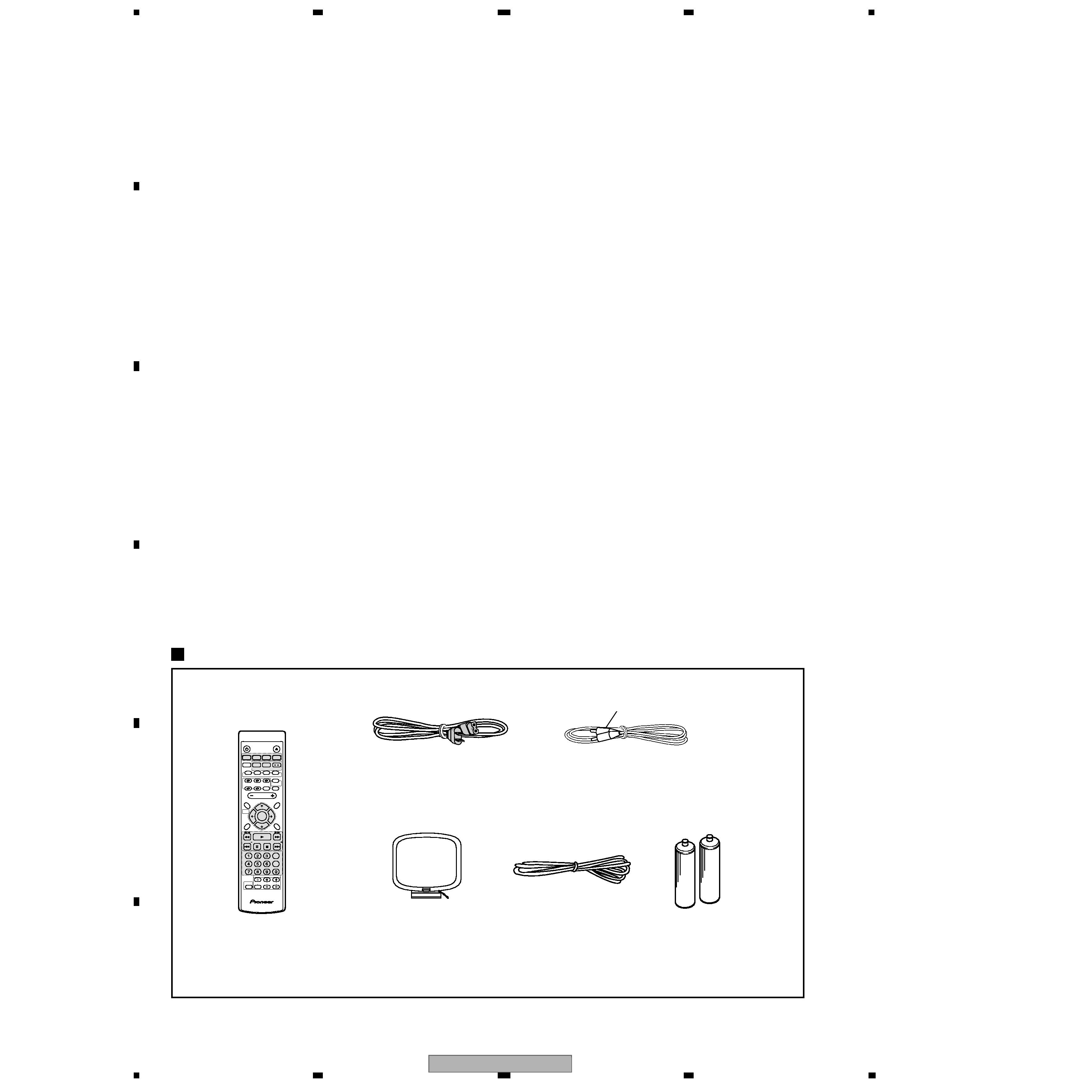
Accessories (DVD/CD receiver)
Remote control . . . . . . . . . . . . . . . . . . . . . . . . . .
1
AA/R6P dry cell batteries . . . . . . . . . . . . . . . . . . . 2
Video cable (yellow plugs) . . . . . . . . . . . . . . . . . . 1
AM loop antenna . . . . . . . . . . . . . . . . . . . . . . . . . . 1
FM antenna . . . . . . . . . . . . . . . . . . . . . . . . . . . . . 1
Power cord. . . . . . . . . . . . . . . . . . . . . . . . . . . . . . . 1
These operating instructions . . . . . . . . . . . . . . . . 1
Warranty Card . . . . . . . . . . . . . . . . . . . . . . . . . . . . 1
Speaker System (S-HTD340)
(Front speakers x2, surround speakers x2, center
speaker x1, subwoofer x1)
Front speakers
Enclosure . . . . . . . . . . Closed-box bookshelf type
(magnetically shielded)
System . . . . . . . . . . . . . . . . . . . . . . .2-way system
Speakers
Woofer . . . . . . . . . . . . . . . . . . 10 cm cone type
Tweeter . . . . . . . . . . . . 3.2 cm semi-dome type
Nominal impedance. . . . . . . . . . . . . . . . . . . . . 6
6
6
6
Frequency range . . . . . . . . . . . . . 60 Hz to 20 kHz
Maximum Input Power. . . . . . . . . . . . . . . . . 100 W
Dimensions . . . . 155 (W) x 360 (H) x 177 (D) mm/
6 1/8 (W) x 143/16 (H) x 615/16 (D) in.
Weight . . . . . . . . . . . . . . . . . . . . . 2.4 kg / 5 lb 5 oz
Center speaker
Enclosure . . . . . . . . . . Closed-box bookshelf type
(magnetically shielded)
System. . . . . . . . . . . . . . . . . .8.7 cm 1-way system
Speakers . . . . . . . . . . . . . . . . . . .8.7 cm cone type
Nominal impedance. . . . . . . . . . . . . . . . . . . . .
Frequency range . . . . . . . . . . . . . 65 Hz to 20 kHz
Maximum Input Power. . . . . . . . . . . . . . . . . 100 W
Dimensions . . . . . 350 (W) x 116 (H) x 98 (D) mm/
13 3/4 (W) x 49/16 (H) x 37/8 (D) in.
Weight . . . . . . . . . . . . . . . . . . . . . .1.6 kg / 3 lb 8 oz
Surround speakers
Enclosure . . . . . . . . . . Closed-box bookshelf type
(magnetically shielded)
System. . . . . . . . . . . . . . . . . .8.7 cm 1-way system
Speakers . . . . . . . . . . . . . . . . . . .8.7 cm cone type
Nominal impedance. . . . . . . . . . . . . . . . . . . . .
Frequency range . . . . . . . . . . . . . 85 Hz to 20 kHz
Maximum Input Power. . . . . . . . . . . . . . . . . 100 W
Dimensions . . . . . 155 (W) x 116 (H) x 98 (D) mm/
6 1/8 (W) x 49/16 (H) x 37/8 (D) in.
Weight . . . . . . . . . . . . . . . . . . . . . . .1 kg / 2 lb 3 oz
Subwoofer
Enclosure. . . . . . . . . . . . . . . Bass-reflexfloor type
System. . . . . . . . . . . . . . . . . .16 cm 1-way system
Speaker . . . . . . . . . . . . . . . . . . . .16 cm cone type
Nominal impedance . . . . . . . . . . . . . . . . . . . . .
Frequency range . . . . . . . . . . . . . . 35 Hz to 2 kHz
Maximum Input Power. . . . . . . . . . . . . . . . . 100 W
Dimensions . . . . 190 (W) x 360 (H) x 327 (D) mm/
7 1/2 (W) x 143/16 (H) x 127/8 (D) in.
Weight . . . . . . . . . . . . . . . . . . . .5.0 kg / 11 lb 0 oz
Accessories (Speaker system)
Speaker cables. . . . . . . . . . . . . . . . . . . . . . . . . . .6
Non-skid pads. . . . . . . . . . . . . . . . . . . . . . .1 sheet
· This product includes FontAvenue ® fonts
licensed by NEC corporation. FontAvenue
is a registered trademark of NEC
Corporation.
· Specifications and design subject to
possible modification without notice, due
to improvements.
Manufactured under license from Dolby
Laboratories. "Dolby", "Pro Logic" and the double-D
symbol are trademarks of Dolby Laboratories.
"DTS" and "DTS Digital Surround" are registered
trademarks of Digital Theater Systems, Inc.

Reviews

There are no reviews of this manual yet.