PIONEER XV-EV61/DLXJ/NC Service Manual

Cover page of PIONEER XV-EV61/DLXJ/NC Service Manual

Service Manual for PIONEER XV-EV61/DLXJ/NC, downloadable as a PDF file.

We also have owner's manual to this model.

Manual details

  • Immediate download after payment.
  • Delivered as a PDF file.
  • The manual has 164 pages
  • File size: 15.84 MB
  • Available language versions: English
  • Different language versions may vary sligthly in file size and page count.

We guarantee that...

  • our manuals are complete,
  • the manual includes circuit diagrams,
  • our manuals are checked with antivirus,
  • We'll issue refund if the manual is damaged, incomplete or unreadable (our refund policy)

Sample pages

Thumbnail of page 1Thumbnail of page 2Thumbnail of page 3Thumbnail of page 4
Thumbnail of page 5Thumbnail of page 6Thumbnail of page 7Thumbnail of page 8
Thumbnail of page 9
background image
ORDER NO.
PIONEER CORPORATION 4-1, Meguro 1-chome, Meguro-ku, Tokyo 153-8654, Japan
PIONEER ELECTRONICS (USA) INC. P.O. Box 1760, Long Beach, CA 90801-1760, U.S.A.
PIONEER EUROPE NV Haven 1087, Keetberglaan 1, 9120 Melsele, Belgium
PIONEER ELECTRONICS ASIACENTRE PTE. LTD. 253 Alexandra Road, #04-01, Singapore 159936
PIONEER CORPORATION 2003
PGM
ADV. SURR. SFC
96k Hz
LINE
REC
RDM RPT ­ 1
MONO
RDS TUNED
STEREO
SUB
Wf
NR B. CUT REC
ASES
REC
WAKE­ UP
KARAOKE L R
ECHO KEY
PRO LOGIC
DIGI TAL
XV-EV61
RRV2793
STEREO DVD TUNER DECK RECEIVER
XV-EV61
XV-EV31
THIS MANUAL IS APPLICABLE TO THE FOLLOWING MODEL(S) AND TYPE(S).
This product is component of system.
Model
Type
Power Requirement
Regionalrestriction
codes (Region No.)
The voltage can be converted
by the following method.
XV-EV61
DLXJ/NC
110-127V/220-230V/240V
3
With the voltage selector
XV-EV31
DLXJ/NC
110-127V/220-230V/240V
3
With the voltage selector
Component
System
System
Service manual
MINI SYSTEM
X-EV61D
X-EV31D
Stereo DVD Tuner Deck Receiver
XV-EV61
XV-EV31
RRV2793(This manual)
Speaker System
S-EV61V
S-EV31V
RRV2776(EV61), RRV2800(EV31)
T-ZZR JULY 2003 printed in Japan
For details, refer to "Important symbols for good services" .
background image
XV-EV61
2
1234
123
4
C
D
F
A
B
E
SAFETY INFORMATION
This service manual is intended for qualified service technicians ; it is not meant for the casual do-
it-yourselfer. Qualified technicians have the necessary test equipment and tools, and have been
trained to properly and safely repair complex products such as those covered by this manual.
Improperly performed repairs can adversely affect the safety and reliability of the product and
may void the warranty. If you are not qualified to perform the repair of this product properly and
safely, you should not risk trying to do so and refer the repair to a qualified service technician.
WARNING !
THE AEL (ACCESSIBLE EMISSION LEVEL) OF THE LASER POWER OUTPUT IS LESS THAN CLASS 1
BUT THE LASER COMPONENT IS CAPABLE OF EMITTING RADIATION EXCEEDING THE LIMIT FOR
CLASS 1.
A SPECIALLY INSTRUCTED PERSON SHOULD DO SERVICING OPERATION OF THE APPARATUS.
LASER DIODE CHARACTERISTICS
FOR DVD : MAXIMUM OUTPUT POWER : 5 mW
WAVELENGTH : 650 nm
FOR CD :
MAXIMUM OUTPUT POWER : 7 mW
WAVELENGTH : 780 nm
Additional Laser Caution
: See page 107
1. Laser Interlock Mechanism
· Loading switch (S101 on the LOAB Assy) is used for interlock
mechanism of the laser.
When this switch turned ON in SW2 (XCLOSE) side (OPEN signal is
0V and XCLOSE signal is 3.5V), a laser becomes the status which
can completely oscillation.
Furthermore, the laser completely oscillates in the disc judgment and
disc playback.
When player is power ON state and laser diode is not completely
oscillating, 780nm laser diode is always oscillating by half power.
· Laser diode is driving with Q101 (650nm LD) and Q102 (780nm LD)
on the DVDM Assy.
Therefore, when short-circuit between the emitter and collector of
these transistors or the base voltage is supplied for transistors turn
on, the laser oscillates. (failure mode)
· In the test mode
, there is the mode that the laser oscillates except
for the disc judgment and playback. LD ON mode in the test mode
oscillates with the laser forcibly.
The interlock mechanism mentioned above becomes invalid in this
mode.
2. When the cover is open, close viewing through the objective lens with
the naked eye will cause exposure to the laser beam.
LABEL CHECK
XV-EV61/DLXJ/NC
(Printed on the Rear Panel B)
SOUND
MODE
AD
VANCED
SURR
OUND
SURR
OUND
ST
ANDBY/ON
ST
. MEMOR
Y
TIMER/CLOCK
ADJ
SYSTEM
DISPLA
Y
ENTER
TIM
ER
KARA
OKE
VOLUME
STEREO
D
VD
CASSETTE
DECK
RECEIVER
EV61
D
VD
FULL
LOGIC
A
UT
O REVERSE
STEREO
CASSETTE
DECK
DVD/CD
TUNER
TAPE
LINE
OPEN/CLOSE
DOLBY
NR
(DEMO)
ASES
MIC
VO
L
PHONES
MA
X
MIN
MA
IN
MIC
SU
B
REVERSE
MODE
REC/ST
OP
PUSH
OPEN
TUNING
­
TUNING
+
4
1
7
3
/
8
¡
¢
PGM
AD
V.S
URR.
SFC
96
kH
z
LINE
REC
RDM
RPT
­ 1
MONO
RDS
TUNED
STEREO
SUB
Wf
NR
B.
CU
T
REC
ASES
REC
WA
KE­
UP
KARA
OKE
L
R
ECHO
KEY
PRO
LO
GIC
DIG
ITA
L
background image
XV-EV61
3
5
678
56
7
8
C
D
F
A
B
E
[ Important symbols for good services ]
In this manual, the symbols shown-below indicate that adjustments, settings or cleaning should be made securely.
When you find the procedures bearing any of the symbols, be sure to fulfill them:
2. Adjustments
To keep the original performances of the product, optimum adjustments or specification confirmation is indispensable.
In accordance with the procedures or instructions described in this manual, adjustments should be performed.
3. Cleaning
For optical pickups, tape-deck heads, lenses and mirrors used in projection monitors, and other parts requiring cleaning,
proper cleaning should be performed to restore their performances.
5. Lubricants, glues, and replacement parts
Appropriately applying grease or glue can maintain the product performances. But improper lubrication or applying
glue may lead to failures or troubles in the product. By following the instructions in this manual, be sure to apply the
prescribed grease or glue to proper portions by the appropriate amount.For replacement parts or tools, the prescribed
ones should be used.
4. Shipping mode and shipping screws
To protect the product from damages or failures that may be caused during transit, the shipping mode should be set or
the shipping screws should be installed before shipping out in accordance with this manual, if necessary.
1. Product safety
You should conform to the regulations governing the product (safety, radio and noise, and other regulations), and
should keep the safety during servicing by following the safety instructions described in this manual.
Discs compatible with this
player
Any disc that displays one of the following
logos should play in this player. Other
formats, including DVD-Audio, DVD-RAM,
DVD-ROM, CD-ROM (except those that
contain MP3 and WMA files), SACD will
not play.
Audio-CD
Fuji Color-CD
DVD-Video
Video-CD
CD-R *
CD-RW *
DVD-R
DVD-RW
Super Video CD (Super VCD)
background image
XV-EV61
4
1234
123
4
C
D
F
A
B
E
CONTENTS
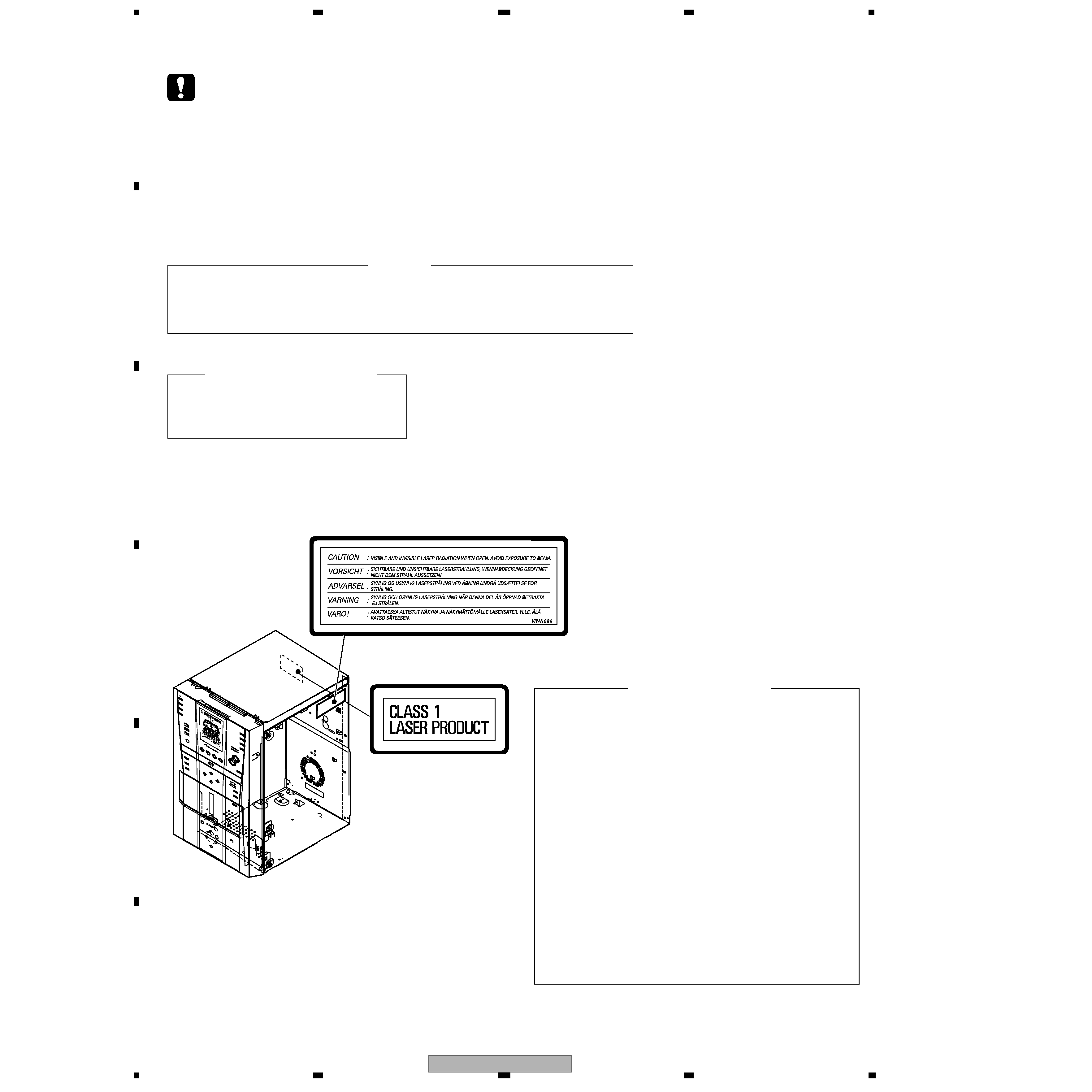
SAFETY INFORMATION ..................................................................................................................................... 2
1. SPECIFICATIONS ............................................................................................................................................ 5
2. EXPLODED VIEWS AND PARTS LIST ............................................................................................................ 6
2.1 PACKING ................................................................................................................................................... 6
2.2 EXTERIOR SECTION................................................................................................................................ 8
2.3 AMP SECTION ........................................................................................................................................ 10
2.4 FRONT PANEL SECTION ....................................................................................................................... 12
2.5 LOADING MECHANISM ASSY ............................................................................................................... 14
2.6 TRAVERSE MECHANISM ASSY............................................................................................................. 16
2.7 DECK MECHANISM ASSY ..................................................................................................................... 18
3. BLOCK DIAGRAM AND SCHEMATIC DIAGRAM ..........................................................................................20
3.1 OVERALL BLOCK DIAGRAM.................................................................................................................. 20
3.2 DVD SECTION BLOCK DIAGRAM .......................................................................................................... 22
3.3 OVERALL WIRING DIAGAM ................................................................................................................... 24
3.4 FM/AM TUNER MODULE ........................................................................................................................ 28
3.5 DVDM ASSY(1/3)..................................................................................................................................... 30
3.6 DVDM ASSY(2/3)..................................................................................................................................... 32
3.7 DVDM ASSY(3/3)..................................................................................................................................... 34
3.8 DECK ASSY ............................................................................................................................................ 36
3.9 IF/AF ASSY(1/3) ...................................................................................................................................... 38
3.10 IF/AF ASSY(2/3) .................................................................................................................................... 40
3.11 IF/AF ASSY(3/3) .................................................................................................................................... 42
3.12 DSP ASSY(1/2)...................................................................................................................................... 44
3.13 DSP ASSY (2/2)..................................................................................................................................... 46
3.14 DISP ASSY ............................................................................................................................................ 48
3.15 MIC ASSY .............................................................................................................................................. 50
3.16 EVOL ASSY ........................................................................................................................................... 52
3.17 MOD. AMP ASSY................................................................................................................................... 54
3.18 SP-TERMINAL and TRADE ASSYS ...................................................................................................... 56
3.19 PRIMARY ASSY .................................................................................................................................... 58
3.20 SECONDARY ASSY .............................................................................................................................. 60
4. PCB CONNECTION DIAGRAM ..................................................................................................................... 62
4.1 LOAB ASSY ............................................................................................................................................. 62
4.2 FM/AM TUNER MODULE ........................................................................................................................ 63
4.3 DVDM ASSY ............................................................................................................................................ 64
4.4 IF/AF ASSY.............................................................................................................................................. 66
4.5 DSP ASSY (XV-EV61 Only)..................................................................................................................... 70
4.6 MIC ASSY ................................................................................................................................................ 71
4.7 DECK ASSY ............................................................................................................................................ 72
4.8 DISP1, DISP2 and DISP3 ASSYS ........................................................................................................... 74
4.9 EVOL ASSY ............................................................................................................................................. 76
4.10 SP-TERMINAL and TRADE ASSYS ...................................................................................................... 80
4.11 MOD. AMP ASSY................................................................................................................................... 82
4.12 PRIMARY ASSY .................................................................................................................................... 84
4.13 SECONDARY......................................................................................................................................... 86
5. PCB PARTS LIST ........................................................................................................................................... 88
6. ADJUSTMENT ............................................................................................................................................. 101
6.1 DECK SECTION .................................................................................................................................... 101
6.1.1 Adjustment condition ....................................................................................................................... 101
6.1.2 Playback and Recording section ..................................................................................................... 102
6.2 TUNER SECTION .................................................................................................................................. 104
6.3 DVD SECTION ADJUSTMENT ITEMS ana LOCATION........................................................................ 105
6.4 JIGS and MEASURING INSTRUMENTS .............................................................................................. 105
6.5 NECESSARY ADJUSTMENT POINTS ................................................................................................. 106
6.6 TEST MODE .......................................................................................................................................... 107
6.7 MECHANISM ADJUSTMENT ................................................................................................................ 108
7. GENERAL INFORMATION ........................................................................................................................... 110
7.1 DIAGNOSIS ........................................................................................................................................... 110
7.2 PARTS.................................................................................................................................................... 145
7.3 CLEANING............................................................................................................................................. 158
8. PANEL FACILITIES ...................................................................................................................................... 159
background image
XV-EV61
5
5
678
56
7
8
C
D
F
A
B
E
1. SPECIFICATIONS
Accessories
Remote control unit
(XXD3060 : EV61)
(XXD3061 : EV31)
AM loop antenna
(ATB7009)
FM wire antenna
AC Power Cord
(ADH7004)
(ADG1154)
AA size IEC R6P
Dry cell batteries (x2)
Specifications
Manufactured
under license from Dolby
Laboratories.
"Dolby" , "Pro Logic" , and the
double-D
symbol are trademarks
of Dolby
Laboratories.
"DTS" and "DTS Digital Sur round" are registered
trademarks
of Digital Theater Systems, Inc.
Manufactured
under license from Digital Theater
Systems,
Inc.
· Specifications and design subject to
possible modification without notice,
due to improvements.
Video Cord
(VDE1065)
Amplifier Section
X-EV61DVD model
Continuous power output:
Front . . . . . . . . . . . . . . . . . . . . . 75 W per channel
(1kHz, 10 % T.H.D., 6
)
Center . . . . . . . . .
75 W (1kHz, 10 % T.H.D., 6
)
Surround . . . . . . . . . . . . . . . . . 75 W per channel
(1kHz, 10 % T.H.D., 6
)
Subwoofer . . . . . 75 W (100Hz, 10 % T.H.D., 6
)
X-EV31DVD model
Front . . . . . . . . . . . . . . . . . . . . . . . . . . 75 W + 75W
(1 kHz, 10 % T.H.D., 6
)
Subwoofer . . . . 100 W (100Hz, 10 % T.H.D., 6
)
Disc section
Digital audio
characteristics
. . . . . . . . . DVD fs: 96 kHz, 24-bit
Type .DVD system, Video CD/Super VCD system
and Compact Disc digital audio system
Frequency response
. . . . . . . . . . . 4 Hz to 44 kHz
S/N ratio . . . . . . . . . . . . . . . . . . . . . . . . . . . .95 dB
Dynamic range
. . . . . . . . . . . . . . . . . . . . . . .95 dB
Total harmonic distortion
. . . . . . . . . . . . . 0.005 %
Wow and Flutter
. . . . . . . . Limit of measurement
(
±0.001 % W.PEAK) or less (JEITA)
Cassette deck section
Systems . . . . . . . . . . . . 4 track, 2-channel stereo
Heads . . . . . . . . . . . Recording/playback head x 1
Erasing head x 1
Motor . . . . . . . . . . . . . . . . . . . DC servo motor x 1
Tape types . . . . . . . . . . . . . . . . . . Type I (Normal)
FM tuner section
Frequency range . . . . . . . . . . . . . . 87.5 ­ 108MHz
Antenna . . . . . . . . . . . . . . . . . . 75
, unbalanced
AM tuner section
Frequency range
With 9 kHz step . . . . . . . . 531 kHz to 1,602 kHz
With 10 kHz step . . . . . . . 530 kHz to 1,700 kHz
Antenna . . . . . . . . . . . . . . . . . . . . . . Loop antenna
Miscellaneous
Power requirements
. . . . . . AC 110-127/220-230/
240 V (switchable), 50/60 Hz
Power consumption
X-EV61DVD model
. . . . . . . . . . . . . . . . . . . . . . . . . . . . . . . . . . 192 W
X-EV31DVD model
. . . . . . . . . . . . . . . . . . . . . . . . . . . . . . . . . . 160 W
Power consumption in standby mode
. . . 0.5 W
Dimensions:
DVD Tuner Deck Receiver
. . . . . . . . . . . . . 170 (W) x 350.5 (H) x 335 (D) mm
Weight:
DVD Tuner Deck Receiver
XV-EV61 . . . . . . . . . . . . . . . . . . . . . . . . . . 8.3 kg
XV-EV31 . . . . . . . . . . . . . . . . . . . . . . . . . . 8.2 kg
Accessories (Stereo DVD Cassette Deck
Receiver)
Remote control
. . . . . . . . . . . . . . . . . . . . . . . . .
1
Power cord
. . . . . . . . . . . . . . . . . . . . . . . 1
Video cord . . . . . . . . . . . . . . . . . . . . . . . . . . . . . . 1
AM loop antenna
. . . . . . . . . . . . . . . . . . . . . . . . . 1
FM antenna
. . . . . . . . . . . . . . . . . . . . . . . . . . . .
1
Dry cell batteries (AA/R6)
. . . . . . . . . . . . . . . . . . 2
Operating instructions
. . . . . . . . . . . . . . .
. . . . . . . . . . . . . . .
2
12
3
45
6
78
9
0
CLEAR
ENTER
SYSTEM
SETUP
HOME MENU
T
OP
MENU
D
VD
MENU
SHIFT
CHANNEL
V
OLUME
INPUT
SUBTITLE
V
OLUME
ANGLE
ZOOM
AD
VANCED
MONO
SYSTEM
DISP
D
VD
DISP
ECHO
DSP
A
UDIO
D
VD/CD
TAPE
FM/AM
LINE
SURR
OUND
PR
OGRAM
TEST
T
ONE
REPEA
T
CH
LEVEL
RANDOM
SLEEP
KARA
OKE
I--
KEYCON
--
i
TIMER
CLOCK
ADJ
.
MUTE
RETURN
FOLDER
+
FOLDER
­
SOUND MODE
ENTER
ST
ANDBY/ON
4
/e
E
/
1
¡
¢
8
7
3
33
TUNE
+
ST
+
ST
­
TUNE
­
DV
D
5.1ch
D
VD
SURR
OUND
SYSTEM
XXD3060
TV
CONTR
OL

Reviews

There are no reviews of this manual yet.