PIONEER XV-EV21/ZDRXJ/RD Service Manual

Cover page of PIONEER XV-EV21/ZDRXJ/RD Service Manual

Service Manual for PIONEER XV-EV21/ZDRXJ/RD, downloadable as a PDF file.

We also have owner's manual to this model.

Manual details

  • Immediate download after payment.
  • Delivered as a PDF file.
  • The manual has 126 pages
  • File size: 12.73 MB
  • Available language versions: English
  • Different language versions may vary sligthly in file size and page count.

We guarantee that...

  • our manuals are complete,
  • the manual includes circuit diagrams,
  • our manuals are checked with antivirus,
  • We'll issue refund if the manual is damaged, incomplete or unreadable (our refund policy)

Sample pages

Thumbnail of page 1Thumbnail of page 2Thumbnail of page 3Thumbnail of page 4
Thumbnail of page 5Thumbnail of page 6Thumbnail of page 7Thumbnail of page 8
Thumbnail of page 9
background image
ORDER NO.
PIONEER CORPORATION 4-1, Meguro 1-chome, Meguro-ku, Tokyo 153-8654, Japan
PIONEER ELECTRONICS (USA) INC. P.O. Box 1760, Long Beach, CA 90801-1760, U.S.A.
PIONEER EUROPE NV Haven 1087, Keetberglaan 1, 9120 Melsele, Belgium
PIONEER ELECTRONICS ASIACENTRE PTE. LTD. 253 Alexandra Road, #04-01, Singapore 159936
PIONEER CORPORATION 2002
SOUND MODE
KARAOKE
VOLUME
ST. MEMORY
TIMER/CLOCK ADJ
DISPLAY
STEREO DVD TUNER DECK
EV51DVD
ENTER
DVD/CD
TUNER
TAPE
LINE
OPEN/CLOSE
DOLBY NR(DEMO)
ASES
MIC VOL
MAX
MIN
MIC
(MAIN)
MIC
(SUB)
REVERSE MODE
REC/STOP
PLAY/PAUSE
STOP
TUNING ­
TUNING +
4/1
¡/¢
­+
XV-EV51
RRV2636
STEREO DVD TUNER DECK
XV-EV51
XV-EV21
THIS MANUAL IS APPLICABLE TO THE FOLLOWING MODEL(S) AND TYPE(S).
This product does not function properly independently; to avoid malfunctions, be sure
to connect it to the prescribed system component(s), otherwise damage may result.
Model
Type
Power Requirement
Regienal restriction
codes (Region No.)
Remarks
XV-EV51
ZLXJ/NC
DC Power supplied from other system component
4
XV-EV21
ZLXJ/NC
DC Power supplied from other system component
4
Component
System
System
Service manual
MINI SYSTEM
EVA-5CH
EVA-2CH
Stereo DVD Tuner Deck
XV-EV51
XV-EV21
RRV2636(This manual)
Stereo Power Amplifier
M-EV51
M-EV21
RRV2663(EV51), RRV2664(EV21)
Speaker System
S-EV51V
S-EV21V
RRV2640(EV51), RRV2641(EV21)
For details, refer to "Important symbols for good services" .
T-ZZR AUG. 2002 printed in Japan
background image
XV-EV51
2
1234
123
4
C
D
F
A
B
E
SAFETY INFORMATION
This service manual is intended for qualified service technicians ; it is not meant for the casual do-
it-yourselfer. Qualified technicians have the necessary test equipment and tools, and have been
trained to properly and safely repair complex products such as those covered by this
manual.Improperly performed repairs can adversely affect the safety and reliability of the product
and may void the warranty. If you are not qualified to perform the repair of this product properly and
safely, you should not risk trying to do so and refer the repair to a qualified service technician.
WARNING !
THE AEL (ACCESSIBLE EMISSION LEVEL) OF THE LASER POWER OUTPUT IS LESS THAN CLASS 1
BUT THE LASER COMPONENT IS CAPABLE OF EMITTING RADIATION EXCEEDING THE LIMIT FOR
CLASS 1.
A SPECIALLY INSTRUCTED PERSON SHOULD DO SERVICING OPERATION OF THE APPARATUS.
LASER DIODE CHARACTERISTICS
FOR DVD : MAXIMUM OUTPUT POWER : 5 mW
WAVELENGTH : 650 nm
FOR CD :
MAXIMUM OUTPUT POWER : 5 mW
WAVELENGTH : 780 nm
Additional Laser Caution
: See page 80.
1. Laser Interlock Mechanism
· Loading switch (S101 on the LOAB Assy) is used for interlock
mechanism of the laser.
When this switch turned ON in SW2 (XCLOSE) side (OPEN signal is
0V and XCLOSE signal is 3.5V), a laser becomes the status which
can completely oscillation.
Furthermore, the laser completely oscillates in the disc judgment and
disc playback.
When player is power ON state and laser diode is not completely
oscillating, 780nm laser diode is always oscillating by half power.
· Laser diode is driving with Q101 (650nm LD) and Q102 (780nm LD)
on the DVDM Assy.
Therefore, when short-circuit between the emitter and collector of
these transistors or the base voltage is supplied for transistors turn
on, the laser oscillates. (failure mode)
· In the test mode
, there is the mode that the laser oscillates except
for the disc judgment and playback. LD ON mode in the test mode
oscillates with the laser forcibly.
The interlock mechanism mentioned above becomes invalid in this
mode.
2. When the cover is open, close viewing through the objective lens with
the naked eye will cause exposure to the laser beam.
LABEL CHECK
XV-EV51/ZLXJ/NC
(Printed on the Rear Panel A)
background image
XV-EV51
3
5
678
56
7
8
C
D
F
A
B
E
[ Important symbols for good services ]
In this manual, the symbols shown-below indicate that adjustments, settings or cleaning should be made securely.
When you find the procedures bearing any of the symbols, be sure to fulfill them:
2. Adjustments
To keep the original performances of the product, optimum adjustments or specification confirmation is indispensable.
In accordance with the procedures or instructions described in this manual, adjustments should be performed.
3. Cleaning
For optical pickups, tape-deck heads, lenses and mirrors used in projection monitors, and other parts requiring cleaning,
proper cleaning should be performed to restore their performances.
5. Lubricants, glues, and replacement parts
Appropriately applying grease or glue can maintain the product performances. But improper lubrication or applying
glue may lead to failures or troubles in the product. By following the instructions in this manual, be sure to apply the
prescribed grease or glue to proper portions by the appropriate amount.For replacement parts or tools, the prescribed
ones should be used.
4. Shipping mode and shipping screws
To protect the product from damages or failures that may be caused during transit, the shipping mode should be set or
the shipping screws should be installed before shipping out in accordance with this manual, if necessary.
1. Product safety
You should conform to the regulations governing the product (safety, radio and noise, and other regulations), and
should keep the safety during servicing by following the safety instructions described in this manual.
Discs compatible with this
player
Any disc that displays one of the following
logos should play in this player. Other
formats, including DVD-Audio, DVD-RAM,
DVD-ROM, CD-ROM (except those that
contain MP3 files), SACD and Photo CD will
not play.
Audio-CD
DVD-Video
Video-CD
* : Video Mode Only
CD-R *
CD-RW *
background image
XV-EV51
4
1234
123
4
C
D
F
A
B
E
CONTENTS
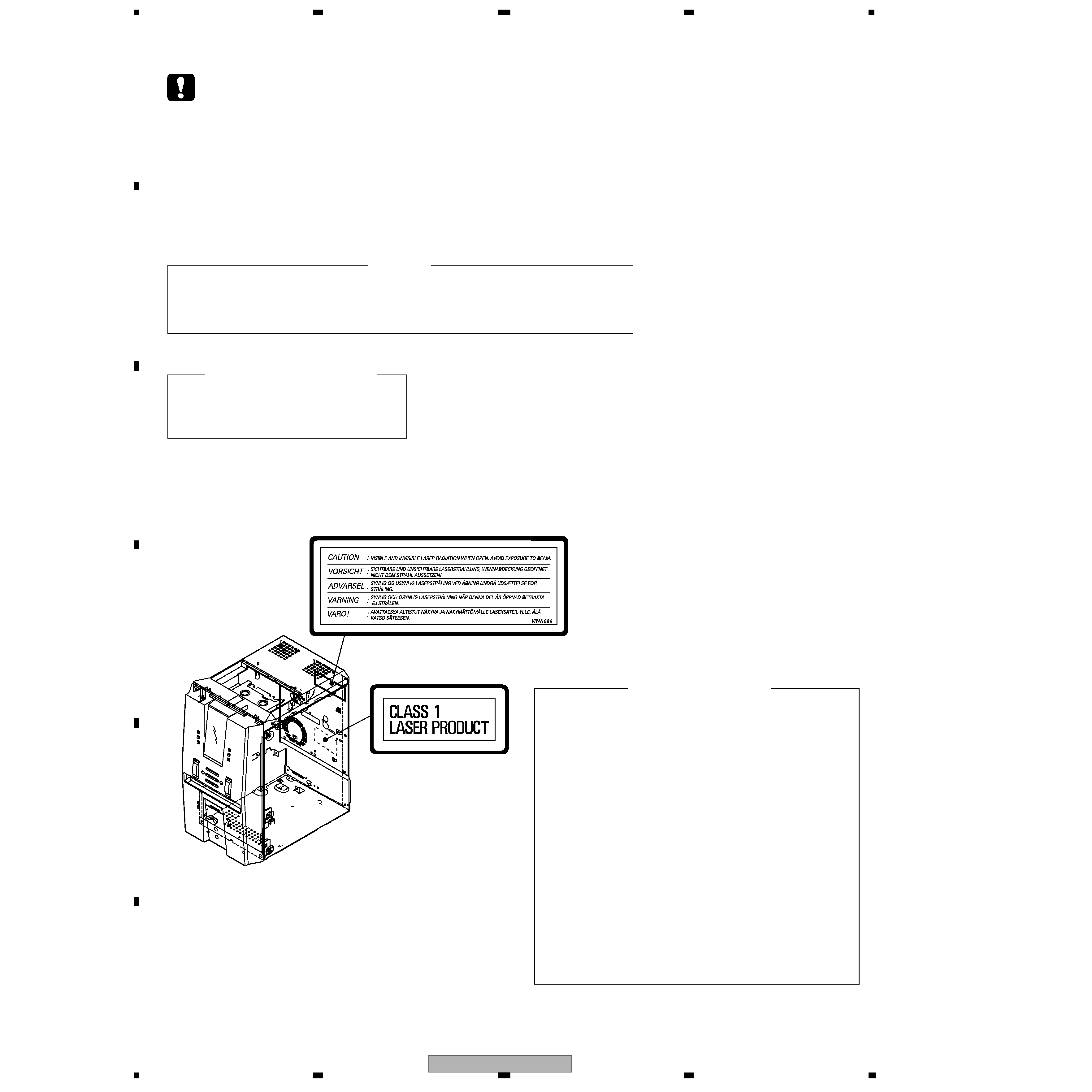
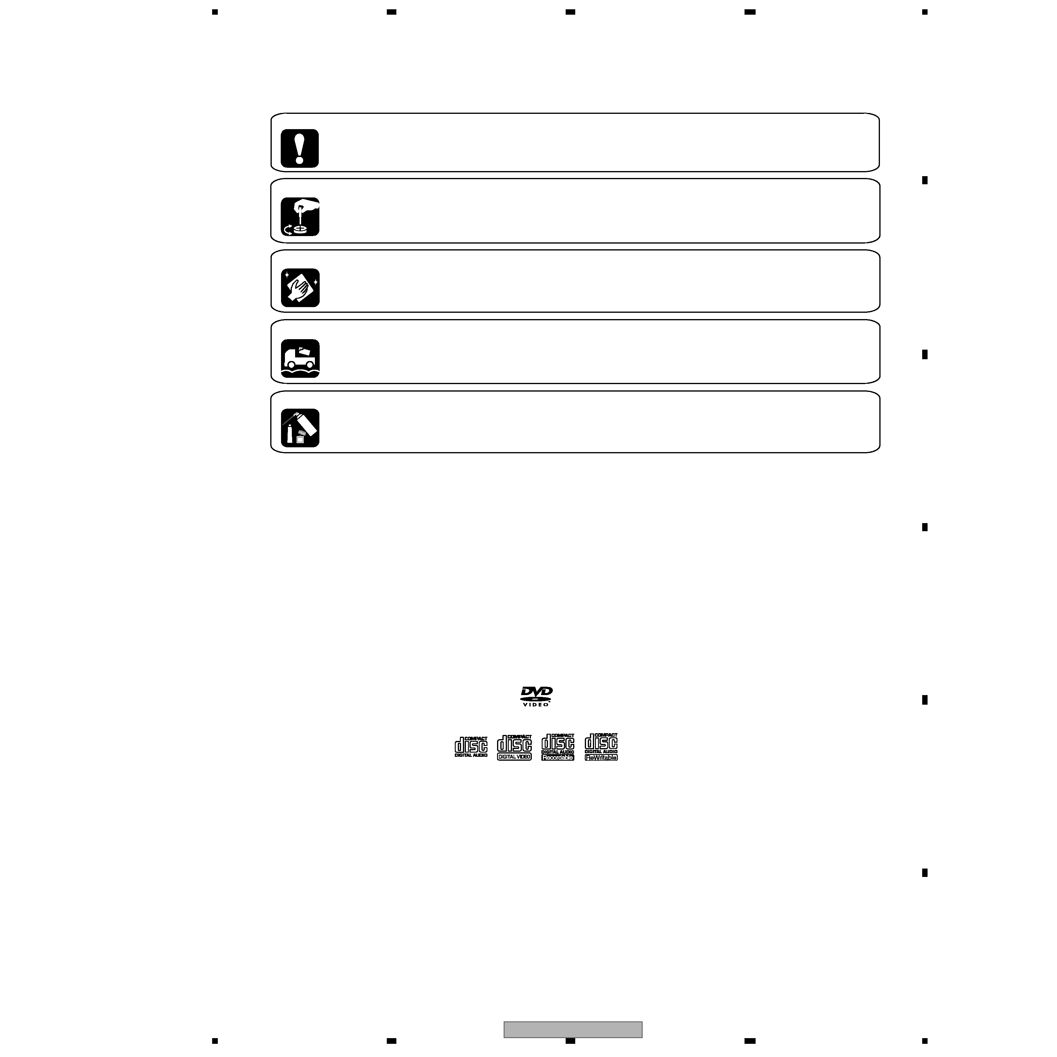
SAFETY INFORMATION ..................................................................................................................................... 2
1. SPECIFICATIONS ............................................................................................................................................ 5
2. EXPLODED VIEWS AND PARTS LIST ............................................................................................................ 6
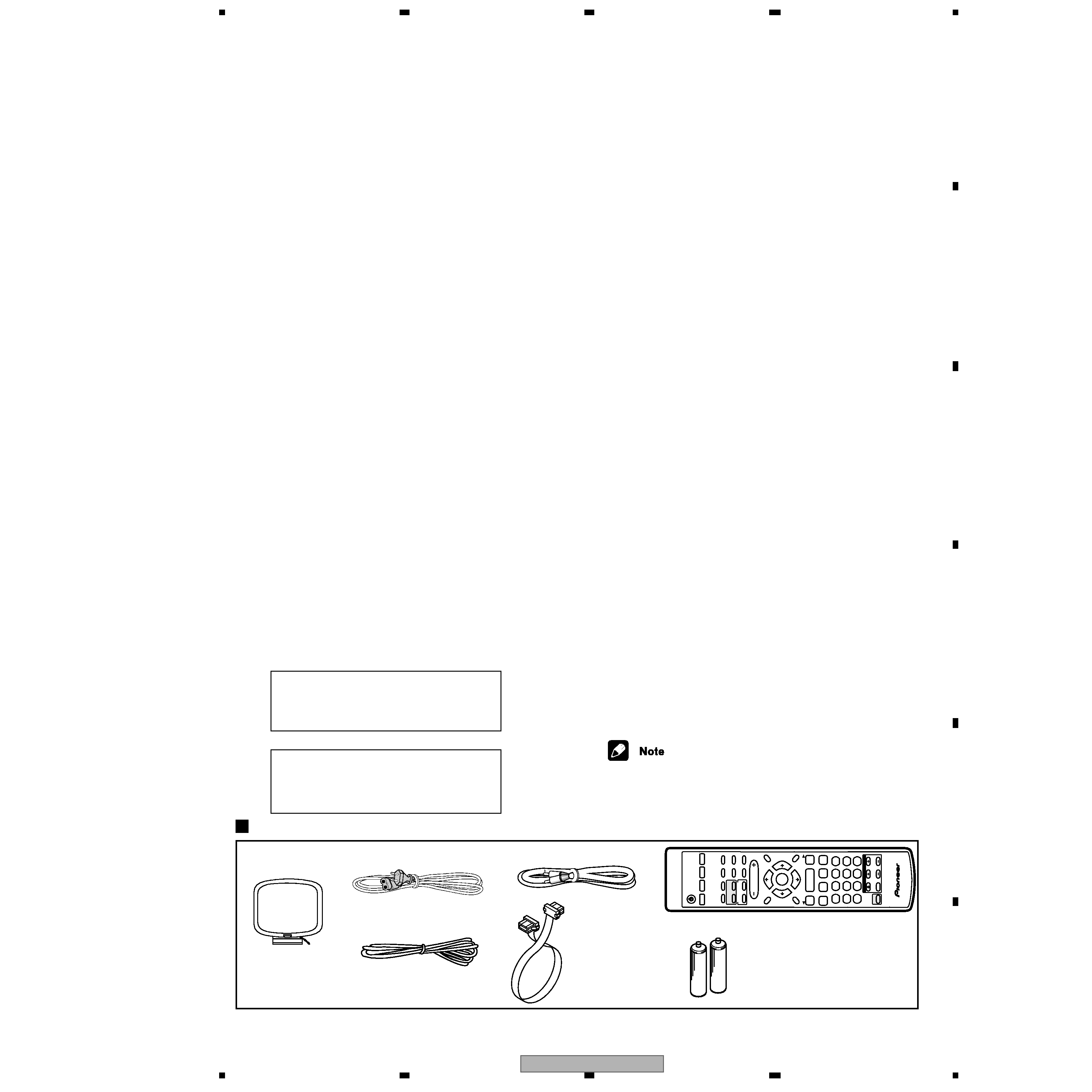
2.1 PACKING ................................................................................................................................................... 6
2.2 EXTERIOR SECTION................................................................................................................................ 8
2.3 FRONT PANEL SECTION ....................................................................................................................... 10
2.4 LOADING MECHANISM ASSY ............................................................................................................... 12
2.5 TRAVERSE MECHANISM ASSY............................................................................................................. 14
3. BLOCK DIAGRAM AND SCHEMATIC DIAGRAM ..........................................................................................16
3.1 BLOCK DIAGRAM ................................................................................................................................... 16
3.2 OVERALL WIRING DIAGAM ................................................................................................................... 20
3.3 FM/AM TUNER MODULE ........................................................................................................................ 24
3.4 IF ASSY ................................................................................................................................................... 26
3.5 AF ASSY(1/2) .......................................................................................................................................... 28
3.6 AF ASSY(2/2) .......................................................................................................................................... 30
3.7 DECK ASSY ............................................................................................................................................ 32
3.8 DVDM ASSY(1/2)..................................................................................................................................... 34
3.9 DVDM ASSY(2/2)..................................................................................................................................... 36
3.10 DVD IF ASSY ......................................................................................................................................... 38
3.11 DISP1, DISP2, DISP3 and LED ASSYS ................................................................................................ 40
3.12 DSP ASSY ............................................................................................................................................. 42
3.13 MIC ASSY .............................................................................................................................................. 44
4. PCB CONNECTION DIAGRAM ..................................................................................................................... 46
4.1 LOAB ASSY ............................................................................................................................................. 46
4.2 FM/AM TUNER MODULE ........................................................................................................................ 47
4.3 DVDM ASSY ............................................................................................................................................ 48
4.4 DVD IF ASSY ........................................................................................................................................... 52
4.5 IF ASSY ................................................................................................................................................... 54
4.6 AF ASSY .................................................................................................................................................. 56
4.7 DECK ASSY ............................................................................................................................................ 58
4.8 DISP1, DISP2, DISP3 and LED ASSYS .................................................................................................. 60
4.9 MIC ASSY ................................................................................................................................................ 62
4.10 DSP ASSY(XV-EV51 Only).................................................................................................................... 63
5. PCB PARTS LIST ........................................................................................................................................... 64
6. ADJUSTMENT ............................................................................................................................................... 72
6.1 DECK SECTION ...................................................................................................................................... 72
6.1.1 Adjustment condition ......................................................................................................................... 72
6.1.2 Playback and Recording section ....................................................................................................... 73
6.2 TUNER SECTION .................................................................................................................................... 75
6.3 DVD SECTION ADJUSTMENT ITEMS ana LOCATION.......................................................................... 76
6.4 JIGS and MEASURING INSTRUMENTS ................................................................................................ 76
6.5 NECESSARY ADJUSTMENT POINTS ................................................................................................... 77
6.6 TEST MODE ............................................................................................................................................ 78
6.7 MECHANISM ADJUSTMENT .................................................................................................................. 79
7. GENERAL INFORMATION ............................................................................................................................. 82
7.1 DIAGNOSIS ............................................................................................................................................. 82
7.2 PARTS.................................................................................................................................................... 101
7.3 CLEANING............................................................................................................................................. 120
8. PANEL FACILITIES ...................................................................................................................................... 121
background image
XV-EV51
5
5
678
56
7
8
C
D
F
A
B
E
1. SPECIFICATIONS
Accessories
(XXD3049)
AM loop antenna
(ATB7009)
FM wire antenna
AC Power Cord
(ADH7004)
(XDG3001)
AA size IEC R6P
Dry cell batteries (x2)
Specifications
Amplifier Section
X-EV51DVD model
Continuous Power Output:
Front ...................................80 W per channel
(1kHz, 10 %, 8
)
Center...................... 33 W (1kHz, 10 %, 8
)
Surround.............................33 W per channel
(1kHz, 10 %, 8
)
X-EV21DVD model
Continuous Power (RMS) ............. 80 W + 80 W
(1 kHz, THD 10%, 8
)
Disc section
Digital audio
characteristics ................DVD fs: 96 kHz,24-bit
Type ........... DVD system, Video CD system and
Compact Disc digital audio system
Frequency response ................... 4 Hz to 44 kHz
S/N ratio....................................................95 dB
Dynamic range ......................................... 95 dB
Total harmonic distortion ..................... 0.005 %
Wow and Flutter..................Limit of measurement
( 0.001 % W.PEAK) or less (EIAJ)
Cassette deck section
Systems.........................4 track, 2-channel stereo
Heads.......................Recording/playback head x 1
Erasing head x 1
Motor ................................... DC servo motor x 1
Tape types ...............................TYPE I (Normal)
FM tuner section
Frequency Range........................87.5 - 108MHz
Antenna ..................................75
, unbalanced
AM tuner section
FrequencyRange
With 9 kHz step .......... 531 kHz to 1,602 kHz
With 10 kHz step ........ 530 kHz to 1,700 kHz
Antenna ........................................Loop antenna
Manufactured under license from Dolby
Laboratories. "Dolby", "Pro Logic", and
the
double-D symbol are trademarks of Dolby
Laboratories.
"DTS" and "DTS Digital Surround" are registered
trademarks of Digital Theater Systems, Inc.
Manufactured under license from Digital Theater
Sy
±
stems, Inc.
Miscellaneous
Power Requirements
Multi voltage model .......
.......
AC 110-127/ 220-230/
Power Consumption
X-EV51DVD model
Singapore, Malaysia, Hong Kong models
..................
..................
..................
..................
175 W
All other model
465 W
X-EV21DVD model
Singapore, Malaysia models .................. 150 W
All other model
540 W
Power Consumption in standby mode .............1 W
Dimensions:
DVD Tuner Deck .................. 170 (W) x292.5(H)
x 260 (D) mm
Power Amplifier ....................... 170 (W) x 190 (H)
x 254 (D) mm
Weight:
DVD Tuner Deck
XV-EV51 ................................................ 3.6 kg
XV-EV21 ................................................ 3.5 kg
Power Amplifier
M-EV51 .................................................. 5.3 kg
M-EV21 .................................................. 4.8 kg
Accessories (Stereo DVD Tuner Deck)
Operating instructions..........................................2
· Specifications and design subject to
possible modification without notice,
due to improvements.
Accessories (Stereo Power Amplifier)
Remote control ....................................................1
Power cord
Australian, New Zealand, Central
and South American models........................... 2
All other models ............................................. 1
Power plug adapter (excluding Singapore,
Hong Kong and Malaysian models)..................... 1
Video cord............................................................ 1
System cable (EV51DVD) ................................... 2
System cable (EV21DVD) ................................... 1
FM antenna.......................................................... 1
AM loop antenna .................................................. 1
Dry cell batteries (AA/R6) ................................... 2
Video Cord
(VDE1034)
System Cable
×1
(XDE3053)
Remote control unit
240V(switchable), 50/60 Hz
TV
CONTR
OL
12
3
45
6
78
9
0
CLEAR
ENTER
SYSTEM
SETUP
D
V
D
SETUP
T
OP
MENU
D
VD
MENU
SHIFT
CHANNEL
V
O
LUME
INPUT
SELECT
SUBTITLE
V
OLUME
ANGLE
ZOOM
AD
V
ANCED
MONO
SYSTEM
DISP
D
V
D
DISP
ECHO
DSP
A
UDIO
D
VD/CD
T
APE
FM/AM
LINE
SURR
OUND
PR
OGRAM
TEST
T
ONE
REPEA
T
CH
LEVEL
RANDOM
SLEEP
KARA
OKE
I
--
KEYCON
--
i
TIMER
CLOCK
ADJ
.
MUTE
RETURN
FOLDER
+
FOLDER
­
SOUND
MODE
ENTER
ST
ANDBY/ON
4
/e
E
/
1
¡
¢
8
7
3
33
TUNE
+
ST
+
ST
­
TUNE
­

Reviews

There are no reviews of this manual yet.