XV-HTD540
3
56
78
56
7
8
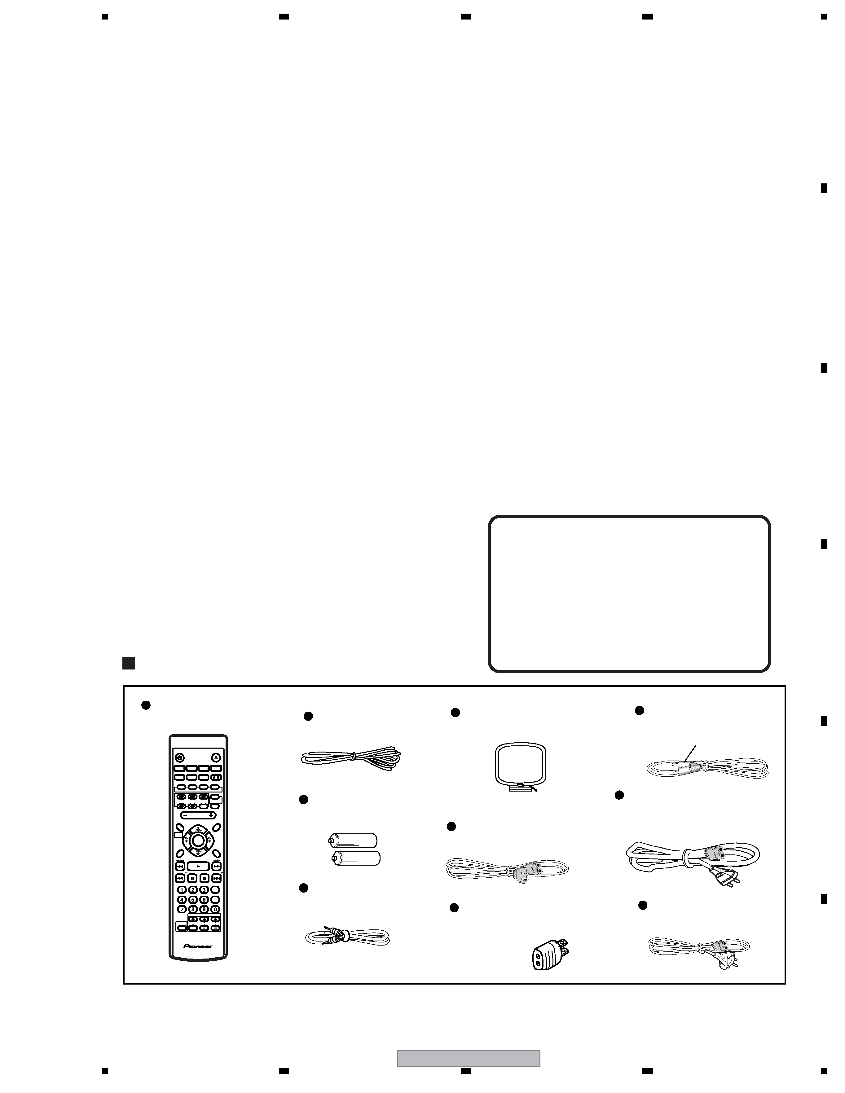
C
D
F
A
B
E
CONTENTS
SAFETY INFORMATION......................................................................................................................................2
1. SPECIFICATIONS .............................................................................................................................................5
2. EXPLODED VIEWS AND PARTS LIST.............................................................................................................6
2.1 PACKING ....................................................................................................................................................6
2.2 EXTERIOR SECTION ................................................................................................................................8
2.3 FRONT PANEL SECTION ........................................................................................................................10
2.4 AMP POWER MODULE ...........................................................................................................................12
2.5 TRAVERSE MECHA ASSY 03-S..............................................................................................................13
2.6 TABLE MECHANISM SECTION ...............................................................................................................14
3. BLOCK DIAGRAM AND SCHEMATIC DIAGRAM ..........................................................................................16
3.1 BLOCK DIAGRAM DVD SECTION...........................................................................................................16
3.2 BLOCK DIAGRAM MAIN SECTION .........................................................................................................18
3.3 OVERALL WIRING DIAGRAM .................................................................................................................20
3.4 DVDM ASSY (1/4) ....................................................................................................................................22
3.5 DVDM ASSY (2/4) ....................................................................................................................................24
3.6 DVDM ASSY (3/4) ....................................................................................................................................26
3.7 DVDM ASSY (4/4) HTD540 Only..............................................................................................................28
3.8 DSP ASSY (1/2) .......................................................................................................................................30
3.9 DSP ASSY (2/2) .......................................................................................................................................32
3.10 6CH AMP ASSY .....................................................................................................................................34
3.11 AF ASSY (1/4) and DVD TRADE ASSY(HTD540 Only) .........................................................................36
3.12 AF ASSY (2/4) ........................................................................................................................................38
3.13 AF(3/4) ASSY .........................................................................................................................................40
3.14 AF(4/4), DIODE L and DIODE S ASSYS................................................................................................42
3.15 TRSB, SSRB, LOMB and SSIB ASSYS .................................................................................................44
3.16 PRIMARY, AMP TRADE, DSP TRADE and VIDEO JACK ASSYS.........................................................46
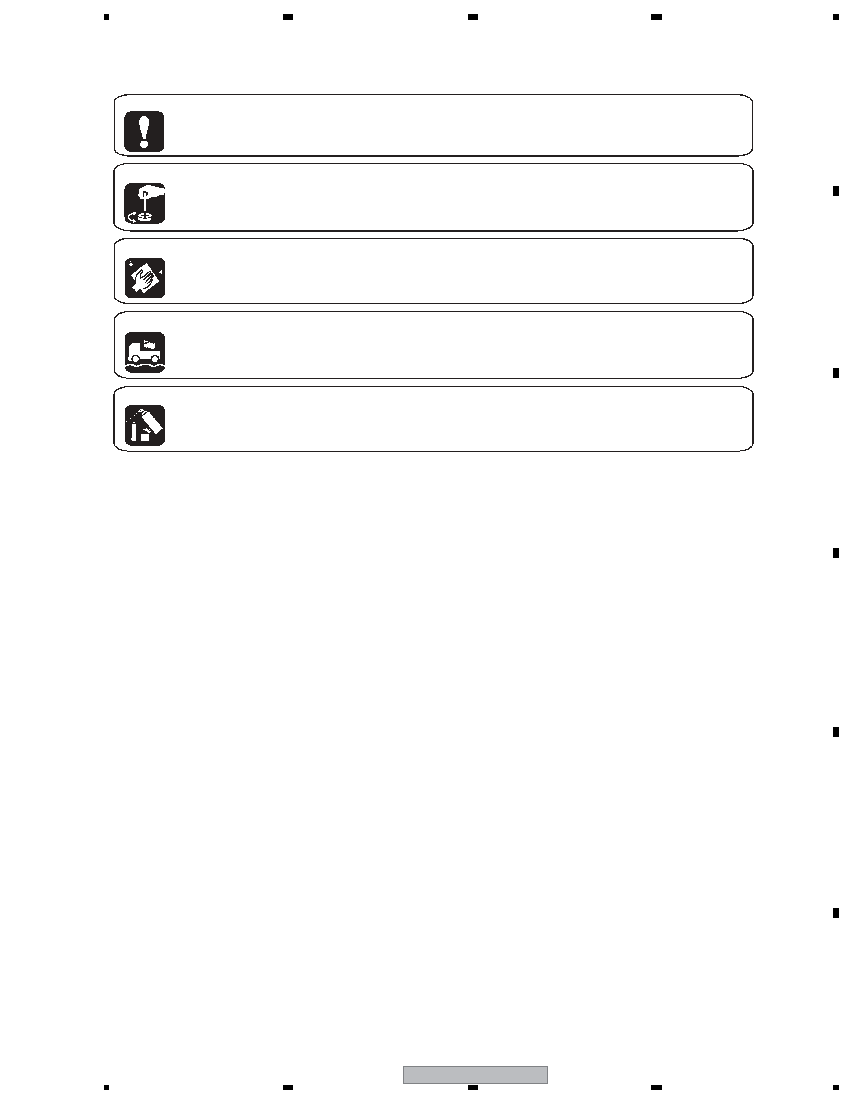
[ Important symbols for good services ]
In this manual, the symbols shown-below indicate that adjustments, settings or cleaning should be made securely.
When you find the procedures bearing any of the symbols, be sure to fulfill them:
2. Adjustments
To keep the original performances of the product, optimum adjustments or specification confirmation is indispensable.
In accordance with the procedures or instructions described in this manual, adjustments should be performed.
3. Cleaning
For optical pickups, tape-deck heads, lenses and mirrors used in projection monitors, and other parts requiring cleaning,
proper cleaning should be performed to restore their performances.
5. Lubricants, glues, and replacement parts
Appropriately applying grease or glue can maintain the product performances. But improper lubrication or applying
glue may lead to failures or troubles in the product. By following the instructions in this manual, be sure to apply the
prescribed grease or glue to proper portions by the appropriate amount.For replacement parts or tools, the prescribed
ones should be used.
4. Shipping mode and shipping screws
To protect the product from damages or failures that may be caused during transit, the shipping mode should be set or
the shipping screws should be installed before shipping out in accordance with this manual, if necessary.
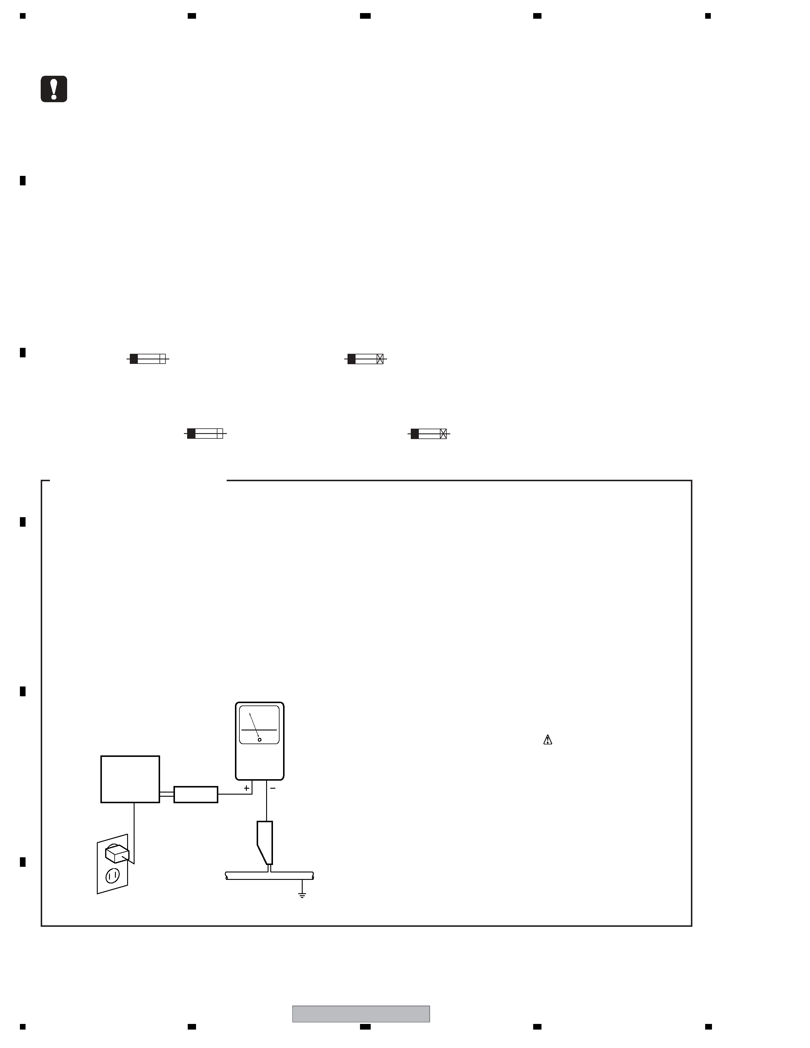
1. Product safety
You should conform to the regulations governing the product (safety, radio and noise, and other regulations), and
should keep the safety during servicing by following the safety instructions described in this manual.