PIONEER XV-DV990/ZYXJ Service Manual

Cover page of PIONEER XV-DV990/ZYXJ Service Manual

Service Manual for PIONEER XV-DV990/ZYXJ, downloadable as a PDF file.

We also have owner's manual to this model.

Manual details

  • Immediate download after payment.
  • Delivered as a PDF file.
  • The manual has 145 pages
  • File size: 7.85 MB
  • Available language versions: English
  • Different language versions may vary sligthly in file size and page count.

We guarantee that...

  • our manuals are complete,
  • the manual includes circuit diagrams,
  • our manuals are checked with antivirus,
  • We'll issue refund if the manual is damaged, incomplete or unreadable (our refund policy)

Sample pages

Thumbnail of page 1Thumbnail of page 2Thumbnail of page 3Thumbnail of page 4
Thumbnail of page 5Thumbnail of page 6Thumbnail of page 7Thumbnail of page 8
Thumbnail of page 9
background image
ORDER NO.
PIONEER CORPORATION 4-1, Meguro 1-chome, Meguro-ku, Tokyo 153-8654, Japan
PIONEER ELECTRONICS (USA) INC. P.O. Box 1760, Long Beach, CA 90801-1760, U.S.A.
PIONEER EUROPE NV Haven 1087, Keetberglaan 1, 9120 Melsele, Belgium
PIONEER ELECTRONICS ASIACENTRE PTE. LTD. 253 Alexandra Road, #04-01, Singapore 159936
PIONEER CORPORATION 2003
TIMER
STANDBY/ON
OPEN/CLOSE
0
XV-DV99
RRV2792
DVD/CD TUNER
XV-DV99
XV-DV990
THIS MANUAL IS APPLICABLE TO THE FOLLOWING MODEL(S) AND TYPE(S).
This product is a system(s) component.
This product does not function properly when independent ; to avoid malfunctions, be sure to
connect it to the prescribed system component(s), otherwise damage may result.
Please connect it to the POWERED SUBWOOFER S-DV99SW/S-DV990SW, for adjustment and
operation inspection.
Model
Type
Power Requirement
Regional restriction
codes (Region No.)
Remarks
XV-DV99
ZYXJ, ZVXJ
DC power supplied from other system component
2
XV-DV990
ZYXJ, ZVXJ
DC power supplied from other system component
2
XV-DV990
RRV2792
S-DV990SW
RRV2811
RRV2806
S-DV990ST
DVD/CD TUNER
POWERED SUBWOOFER
SPEAKER SYSTEM
This manual
Component
System
Service Manual
Remarks
XV-DV99
RRV2792
S-DV99
S-DV99SW
RRV2807
S-DV99ST
DVD/CD TUNER
SPEAKER SYSTEM
POWERED SUBWOOFER
SPEAKER SYSTEM
This manual
Component
System
Service Manual
Remarks
For details, refer to "Important symbols for good services" .
T-ZZV JULY 2003 printed in Japan
background image
XV-DV99
2
1234
123
4
C
D
F
A
B
E
SAFETY INFORMATION
WARNING !
THE AEL (ACCESSIBLE EMISSION LEVEL) OF THE LASER POWER OUTPUT IS LESS THAN CLASS 1
BUT THE LASER COMPONENT IS CAPABLE OF EMITTING RADIATION EXCEEDING THE LIMIT FOR
CLASS 1.
A SPECIALLY INSTRUCTED PERSON SHOULD DO SERVICING OPERATION OF THE APPARATUS.
LASER DIODE CHARACTERISTICS
FOR DVD : MAXIMUM OUTPUT POWER : 5 mW
WAVELENGTH : 650 nm
FOR CD :
MAXIMUM OUTPUT POWER : 7 mW
WAVELENGTH : 780 nm
Additional Laser Caution
: See page 74.
1. Laser Interlock Mechanism
· Loading switch (S101 on the LOAB Assy) is used for interlock
mechanism of the laser.
When this switch turned ON in SW2 (XCLOSE) side (OPEN signal is
0V and XCLOSE signal is 3.5V), a laser becomes the status which
can completely oscillation.
Furthermore, the laser completely oscillates in the disc judgment and
disc playback.
When player is power ON state and laser diode is not completely
oscillating, 780nm laser diode is always oscillating by half power.
· Laser diode is driving with Q201 (650nm LD) and Q211 (780nm LD)
on the DVDM Assy.
Therefore, when short-circuit between the emitter and collector of
these transistors or the base voltage is supplied for transistors turn
on, the laser oscillates. (failure mode)
· In the test mode
, there is the mode that the laser oscillates except
for the disc judgment and playback. LD ON mode in the test mode
oscillates with the laser forcibly.
The interlock mechanism mentioned above becomes invalid in this
mode.
2. When the cover is open, close viewing through the objective lens with
the naked eye will cause exposure to the laser beam.
LABEL CHECK
Name Label
VRW1872
This service manual is intended for qualified service technicians; it is not meant for the casual
do-it-yourselfer. Qualified technicians have the necessary test equipment and tools, and have been
trained to properly and safely repair complex products such as those covered by this manual.
Improperly performed repairs can adversely affect the safety and reliability of the product and may
void the warranty. If you are not qualified to perform the repair of this product properly and safely, you
should not risk trying to do so and refer the repair to a qualified service technician.
background image
XV-DV99
3
5
678
56
7
8
C
D
F
A
B
E
[ Important symbols for good services ]
In this manual, the symbols shown-below indicate that adjustments, settings or cleaning should be made securely.
When you find the procedures bearing any of the symbols, be sure to fulfill them:
2. Adjustments
To keep the original performances of the product, optimum adjustments or specification confirmation is indispensable.
In accordance with the procedures or instructions described in this manual, adjustments should be performed.
3. Cleaning
For optical pickups, tape-deck heads, lenses and mirrors used in projection monitors, and other parts requiring cleaning,
proper cleaning should be performed to restore their performances.
5. Lubricants, glues, and replacement parts
Appropriately applying grease or glue can maintain the product performances. But improper lubrication or applying
glue may lead to failures or troubles in the product. By following the instructions in this manual, be sure to apply the
prescribed grease or glue to proper portions by the appropriate amount.For replacement parts or tools, the prescribed
ones should be used.
4. Shipping mode and shipping screws
To protect the product from damages or failures that may be caused during transit, the shipping mode should be set or
the shipping screws should be installed before shipping out in accordance with this manual, if necessary.
1. Product safety
You should conform to the regulations governing the product (safety, radio and noise, and other regulations), and
should keep the safety during servicing by following the safety instructions described in this manual.
* When the FFC cable between the VIDEO ASSY-CN8301 and DVDM ASSY-CN 943 is off from
the connector and then the power is turned on, the parts below on the DVDM ASSY may be
destroyed.
Be sure to take care when diagnosing the ASSYS. Refer to P.106.
IC851
DSD1791DBR (AUDIO DAC)
IC861, IC871
DSD1702EG (AUDIO DAC)
background image
XV-DV99
4
1234
123
4
C
D
F
A
B
E
CONTENTS
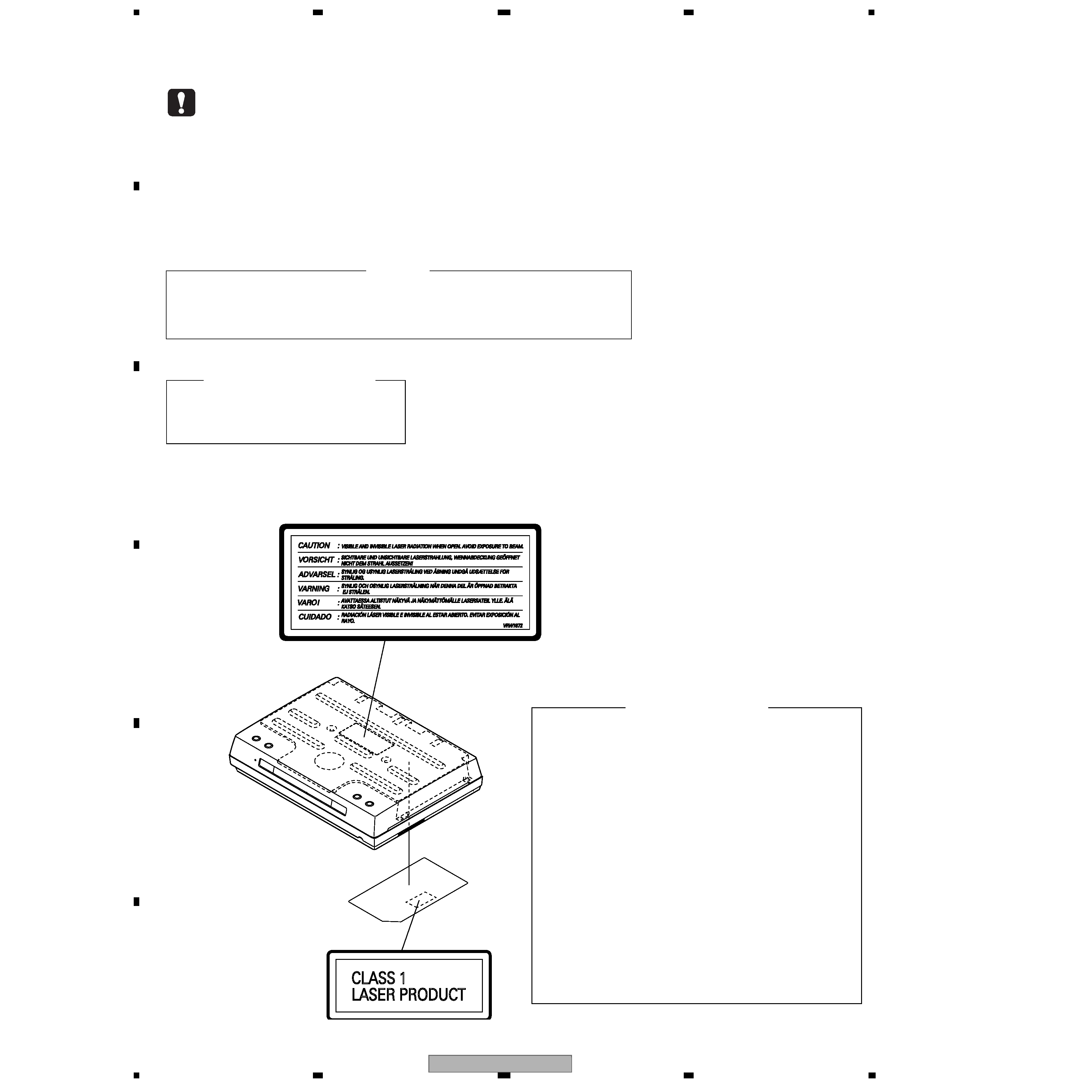
SAFETY INFORMATION ..................................................................................................................................... 2
1. SPECIFICATIONS ............................................................................................................................................ 5
2. EXPLODED VIEWS AND PARTS LIST ............................................................................................................ 8
2.1 PACKING ................................................................................................................................................... 8
2.2 EXTERIOR SECTION.............................................................................................................................. 10
2.3 LOADING MECHA ASSY ........................................................................................................................ 12
2.4 TRAVERSE MECHA ASSY-S .................................................................................................................. 14
2.5 DISPLAY UNIT ......................................................................................................................................... 15
3. BLOCK DIAGRAM AND SCHEMATIC DIAGRAM ..........................................................................................16
3.1 BLOCK DIAGRAM ................................................................................................................................... 16
3.2 LOAB ASSY and OVERALL WIRING DIAGRAM..................................................................................... 18
3.3 DVDM ASSY(1/4)..................................................................................................................................... 20
3.4 DVDM ASSY(2/4)..................................................................................................................................... 22
3.5 DVDM ASSY(3/4)..................................................................................................................................... 24
3.6 DVDM ASSY(4/4)..................................................................................................................................... 26
3.7 VIDEO and DSP TRADE ASSYS............................................................................................................. 28
3.8 DSP ASSY(1/2)........................................................................................................................................ 30
3.9 DSP ASSY(2/2)........................................................................................................................................ 32
3.10 FM/AM TUNER MODULE ...................................................................................................................... 34
3.11 TATRADE and CONTROL(1/3) ASSYS ................................................................................................. 36
3.12 CONTROL(2/3) and HP ASSYS ............................................................................................................ 38
3.13 CONTROL ASSY(3/3)............................................................................................................................ 40
3.14 LCDCONT, CONNECT, KEY RTOP, KEY R, KEY L and KEY LTOP ASSYS ........................................ 42
3.15 WAVEFORMS ........................................................................................................................................ 44
4. PCB CONNECTION DIAGRAM ..................................................................................................................... 45
4.1 LOAB ASSY ............................................................................................................................................. 45
4.2 DVDM ASSY ............................................................................................................................................ 46
4.3 VIDEO and DSP TRADE ASSYS............................................................................................................. 48
4.4 DSP ASSY ............................................................................................................................................... 52
4.5 FM/AM TUNER MODULE ........................................................................................................................ 54
4.6 KEY RTOP, KEY R, KEY L and KEY LTOP ASSYS................................................................................. 55
4.7 TXTRADE, CONTROL and HP ASSYS ................................................................................................... 56
4.8 LCDCONT and CONNECT ASSYS ......................................................................................................... 60
5. PCB PARTS LIST ........................................................................................................................................... 62
6. ADJUSTMENT ............................................................................................................................................... 68
6.1 TUNER SECTION .................................................................................................................................... 68
6.2 ADJUSTMENT ITEMS AND LOCATION ................................................................................................. 69
6.3 JIGS AND MEASURING INSTRUMENTS ............................................................................................... 69
6.4 NECESSARY ADJUSTMENT POINTS ................................................................................................... 70
6.5 TEST MODE ............................................................................................................................................ 71
6.6 MECHANISM ADJUSTMENT .................................................................................................................. 72
7. GENERAL INFORMATION ............................................................................................................................. 74
7.1 DIAGNOSIS ............................................................................................................................................. 74
7.1.1 TEST MODE ......................................................................................................................................... 74
7.1.2 DISPLAY SPECIFICATIONS OF THE TEST MODE ............................................................................. 76
7.1.3 FUNCTIONAL SPECIFICATION OF THE SHORTCUT KEY ................................................................ 77
7.1.4 SPECIFICATION OF MODEL INFORMATION ..................................................................................... 78
7.1.5 FUNCTIONAL SPECIFICATION OF THE SERVICE MODE................................................................. 79
7.1.6 MECHANICAL ERROR HISTORY ........................................................................................................ 80
7.1.7 ID NUMBER AND DATA SETTING ....................................................................................................... 85
7.1.8 TROUBLE SHOOTING ......................................................................................................................... 88
7.1.9 DSP TROUBLE SHOOTING ................................................................................................................. 91
7.1.10 SEQUENCE AFTER POWER ON ...................................................................................................... 95
7.1.11 SINGLE OPERATION METHOD....................................................................................................... 100
7.1.12 PROTECTION CIRCUIT ................................................................................................................... 101
7.1.13 DISASSEMBLY ................................................................................................................................. 105
7.2 IC ........................................................................................................................................................... 114
7.3 DISC/CONTENT FORMAT .................................................................................................................... 137
7.4 CLEANING............................................................................................................................................. 139
8. PANEL FACILITIES ...................................................................................................................................... 140
background image
XV-DV99
5
5
678
56
7
8
C
D
F
A
B
E
1. SPECIFICATIONS
Amplifier Section
Continuous Power (RMS). . . . . 75 W / channel
. . . . . . . . . . . . . . . . . . . . (1 kHz, THD 10%, 6
)
Disc section
Digital audio
characteristics . . . . . . . DVD fs: 96 kHz, 24-bit
Type. . . . . .DVD system, Video CD system and
Compact Disc digital audio system
Frequency response
48 kHz sampling. . . . . . . . . . 4 Hz ­ 22 kHz
96 kHz sampling. . . . . . . . . . 4 Hz ­ 44 kHz
192 kHz sampling. . . . . . . . . 4 Hz ­ 88 kHz
S/N ratio . . . . . . . . . . . . . . . . . . . . . . . . 108dB
Dynamic range . . . . . . . . . . . . . . . . . . . 95dB
Total harmonic distortion . . . . . . . . . . .0.005 %
Wow and Flutter. . . . . . .Limit of measurement
(
±0.001 % W.PEAK) or less (JEITA)
FM tuner section
Frequency Range. . . . . . . . . . . . .87.5 - 108MHz
Antenna . . . . . . . . . . . . . . . .75
, unbalanced
AM tuner section
Frequency Range. . . . . . . 531 kHz to 1,602 kHz
Antenna . . . . . . . . . . . . . . . . . . . Loop antenna
Miscellaneous
Power Requirements
European model. . AC 220 - 230 V, 50/60 Hz
U.K. model. . . . . . . . . . . AC 230V, 50/60 Hz
Power Consumption . . . . . . . . . . . . . . . .163 W
Power Consumption
in standby mode . . . . . . . . . . . . . . . . . . .0.48 W
Dimensions:
DVD/CD Tuner. .360 (W) x 74 (H) x 270 (D) mm
Display Unit . . . . 274 (W) x 44 (H) x 35 (D) mm
Weight:
DVD/CD Tuner. . . . . . . . . . . . . . . . . . . . 3.2 kg
Display Unit . . . . . . . . . . . . . . . . . . . . . . 0.2 kg
Accessories
Operating Instructions . . . . . . . . . . . . . . . . . . 1
Setup guide. . . . . . . . . . . . . . . . . . . . . . . . . . 1
Display unit . . . . . . . . . . . . . . . . . . . . . . . . . . 1
Remote control unit . . . . . . . . . . . . . . . . . . . . 1
Power cord . . . . . . . . . . . . . . . . . . . . . . . . . . 1
Video Cord (yellow plugs) . . . . . . . . . . . . . . . 1
Display cable (gray plugs). . . . . . . . . . . . . . . 1
Control cable A (blue plugs) . . . . . . . . . . . . . 1
Control cable B (black plugs) . . . . . . . . . . . . .1
FM antenna . . . . . . . . . . . . . . . . . . . . . . . . . . .
1
AM loop antenna . . . . . . . . . . . . . . . . . . . . . . 1
Dry cell batteries (AA/R6) . . . . . . . . . . . . . . . 2
Speaker cords (5 m). . . . . . . . . . . . . . . . . . . . 3
Speaker cords (10 m). . . . . . . . . . . . . . . . . . . 2
Non-skid pads (center speaker) . . . . . . . . . . . 3
Non-skid pads (subwoofer). . . . . . . . . . . . . . 4
Speaker stands. . . . . . . . . . . . . . . . . . . . . . . 4
Warranty Card. . . . . . . . . . . . . . . . . . . . . . . . 1
Satellite Speaker System
(S-DV99ST)
Type Sealed, antimagnetic
Speaker . . . . . . . . . . . . . . . . .
8.7 cm (cone type)
. . . . . . . . . . . . . . . . . . . . . . . .
5.2 cm (cone type)
Nominal impedence . . . . . . . . . . . . . . . . . . 6
Frequency range. . . . . . . . . . . .80 ­ 20,000 Hz
Max. input . . . . . . . . . . . . . . . . . . 75 W (JEITA)
Front / Surround speakers
Dimensions . . . . .110 (W) x 59 (D) x 284 (H) cm
Weight . . . . . . . . . . . . . . . . . . . . . . . . . . 0.7 kg
Center speaker
Dimensions . . . . .284 (W) x 58 (D) x 110 (H) cm
Weight . . . . . . . . . . . . . . . . . . . . . . . . . . 0.7 kg
Satellite Speaker System
(S-DV990ST)
Type . . . . . . . . . . . . . Flat panel type bookshelf
Speaker
Exciter. . . . . . . . . . . . . . . 2.5 cm exciter x 3
Tweeter. . . . . . . . . . . . . . .2.6 cm (cone type)
Nominal impedence . . . . . . . . . . . . . . . . . . 6
Frequency range. . . . . . . . . . . .100 ­ 35,000 Hz
Max. input . . . . . . . . . . . . . . . . . . 75 W (JEITA)
Front / Surround speakers
Dimensions . . . . .120 (W) x 30 (D) x 450 (H) cm
Weight . . . . . . . . . . . . . . . . . . . . . . . . . . 0.9 kg
Center speaker
Dimensions . . . . .420 (W) x 32 (D) x 120 (H) cm
Weight . . . . . . . . . . . . . . . . . . . . . . . . . . 0.9 kg
Powered subwoofer
(S-DV99SW S-DV990SW)
Type . . . . . .Bass reflex floor type, antimagnetic
Speaker . . . . . . . . . . . . . . . . 18 cm (cone type)
Nominal impedence . . . . . . . . . . . . . . . . . . 6
Frequency range. . . . . . . . . . . . . . . 28 ­ 250 Hz
Max. input . . . . . . . . . . . . . . . . . . 75 W (JEITA)
Dimensions . . . .192 (W) x 436 (D) x 395 (H) cm
Weight . . . . . . . . . . . . . . . . . . . . . . . . . .12.5 kg

Reviews

There are no reviews of this manual yet.