PIONEER XVDV820 Service Manual

Cover page of PIONEER XVDV820 Service Manual

Service Manual for PIONEER XVDV820, downloadable as a PDF file.

Manual details

  • Immediate download after payment.
  • Delivered as a PDF file.
  • The manual has 125 pages
  • File size: 12.81 MB
  • Available language versions: English
  • Different language versions may vary sligthly in file size and page count.

We guarantee that...

  • our manuals are complete,
  • the manual includes circuit diagrams,
  • our manuals are checked with antivirus,
  • We'll issue refund if the manual is damaged, incomplete or unreadable (our refund policy)

Sample pages

Thumbnail of page 1Thumbnail of page 2Thumbnail of page 3Thumbnail of page 4
Thumbnail of page 5Thumbnail of page 6Thumbnail of page 7Thumbnail of page 8
Thumbnail of page 9
background image
ORDER NO.
PIONEER CORPORATION 4-1, Meguro 1-chome, Meguro-ku, Tokyo 153-8654, Japan
PIONEER ELECTRONICS (USA) INC. P.O. Box 1760, Long Beach, CA 90801-1760, U.S.A.
PIONEER EUROPE NV Haven 1087, Keetberglaan 1, 9120 Melsele, Belgium
PIONEER ELECTRONICS ASIACENTRE PTE. LTD. 253 Alexandra Road, #04-01, Singapore 159936
PIONEER CORPORATION 2002
RRV2683
DVD / CD RECEIVER
XV-DV820
T ­ ZZV SEPT. 2002 Printed in Japan
Type
Model
Power Requirement
Region No.
Remarks
XV-DV820
XV-DV620
KUCXJN
AC120V
1
THIS MANUAL IS APPLICABLE TO THE FOLLOWING MODEL(S) AND TYPE(S).
OPEN/CLOSE
DVD/CD
FM/AM
DOWN
VOLUME
UP
STANDBY/ON
PHONES
6
0
TUNER
--
+
For details, refer to "Important symbols for good services" on the next page.
XV-DV620
background image
2
1
23
4
12
3
4
C
D
F
A
B
E
XV-DV820, XV-DV620
SAFETY INFORMATION
This service manual is intended for qualified service technicians; it is not meant for the casual
do-it-yourselfer. Qualified technicians have the necessary test equipment and tools, and have been
trained to properly and safely repair complex products such as those covered by this manual.
Improperly performed repairs can adversely affect the safety and reliability of the product and may
void the warranty. If you are not qualified to perform the repair of this product properly and safely, you
should not risk trying to do so and refer the repair to a qualified service technician.
WARNING
This product contains lead in solder and certain electrical parts contain chemicals which are known to the state of California to
cause cancer, birth defects or other reproductive harm.
Health & Safety Code Section 25249.6 ­ Proposition 65
NOTICE
(FOR CANADIAN MODEL ONLY)
Fuse symbols
(fast operating fuse)
and/or
(slow operating fuse) on PCB indicate that replacement
parts must be of identical designation.
REMARQUE
(POUR MODÈLE CANADIEN SEULEMENT)
Les symboles de fusible
(fusible de type rapide)
et/ou
(fusible de type lent) sur CCI indiquent que
les pièces de remplacement doivent avoir la même désignation.
ANY MEASUREMENTS NOT WITHIN THE
LIMITS OUTLINED ABOVE ARE INDICATIVE
OF A POTENTIAL SHOCK HAZARD AND
MUST BE CORRECTED BEFORE RETURN-
ING THE APPLIANCE TO THE CUSTOMER.
2. PRODUCT SAFETY NOTICE
Many electrical and mechanical parts in the appliance
have special safety related characteristics. These are
often not evident
from visual
inspection nor the
protection afforded by them necessarily can be obtained
by using replacement components rated for voltage,
wattage, etc. Replacement parts which have these
special safety characteristics are identified in this
Service Manual.
Electrical components having such features are
identified by marking with a
on the schematics and
on the parts list in this Service Manual.
The use of a substitute replacement component which
does not have the same safety characteristics as the
PIONEER recommended replacement one, shown in the
parts list in this Service Manual, may create shock, fire,
or other hazards.
Product Safety is continuously under review and new
instructions are issued from time to time. For the latest
information, always consult the current PIONEER
Service Manual. A subscription to, or
additional copies
of, PIONEER Service Manual may be obtained at a
nominal charge from PIONEER.
(FOR USA MODEL ONLY)
1. SAFETY PRECAUTIONS
The following check should be performed for the
continued protection of the customer and service
technician.
LEAKAGE CURRENT CHECK
Measure leakage current to a known earth ground
(water pipe, conduit, etc.) by connecting a leakage
current tester such as Simpson Model 229-2 or
equivalent between the earth ground and all exposed
metal parts of the appliance (input/output terminals,
screwheads, metal overlays, control shaft, etc.). Plug
the AC line cord of the appliance directly into a 120V
AC 60 Hz outlet and turn the AC power switch on. Any
current measured must not exceed 0.5 mA.
Device
under
test
Leakage
current
tester
Earth
ground
Reading should
not be above
0.5 mA
Also test with
plug reversed
(Using AC adapter
plug as required)
Test all
exposed metal
surfaces
AC Leakage Test
background image
3
1
23
4
1
2
3
4
C
D
F
A
B
E
XV-DV820, XV-DV620
[ Important symbols for good services ]
In this manual, the symbols shown-below indicate that adjustments, settings or cleaning should be made securely.
When you find the procedures bearing any of the symbols, be sure to fulfill them:
2. Adjustments
To keep the original performances of the product, optimum adjustments or specification confirmation is indispensable.
In accordance with the procedures or instructions described in this manual, adjustments should be performed.
3. Cleaning
For optical pickups, tape-deck heads, lenses and mirrors used in projection monitors, and other parts requiring cleaning,
proper cleaning should be performed to restore their performances.
5. Lubricants, glues, and replacement parts
Appropriately applying grease or glue can maintain the product performances. But improper lubrication or applying
glue may lead to failures or troubles in the product. By following the instructions in this manual, be sure to apply the
prescribed grease or glue to proper portions by the appropriate amount.For replacement parts or tools, the prescribed
ones should be used.
4. Shipping mode and shipping screws
To protect the product from damages or failures that may be caused during transit, the shipping mode should be set or
the shipping screws should be installed before shipping out in accordance with this manual, if necessary.
1. Product safety
You should conform to the regulations governing the product (safety, radio and noise, and other regulations), and
should keep the safety during servicing by following the safety instructions described in this manual.
background image
4
1
23
4
12
3
4
C
D
F
A
B
E
XV-DV820, XV-DV620
CONTENTS
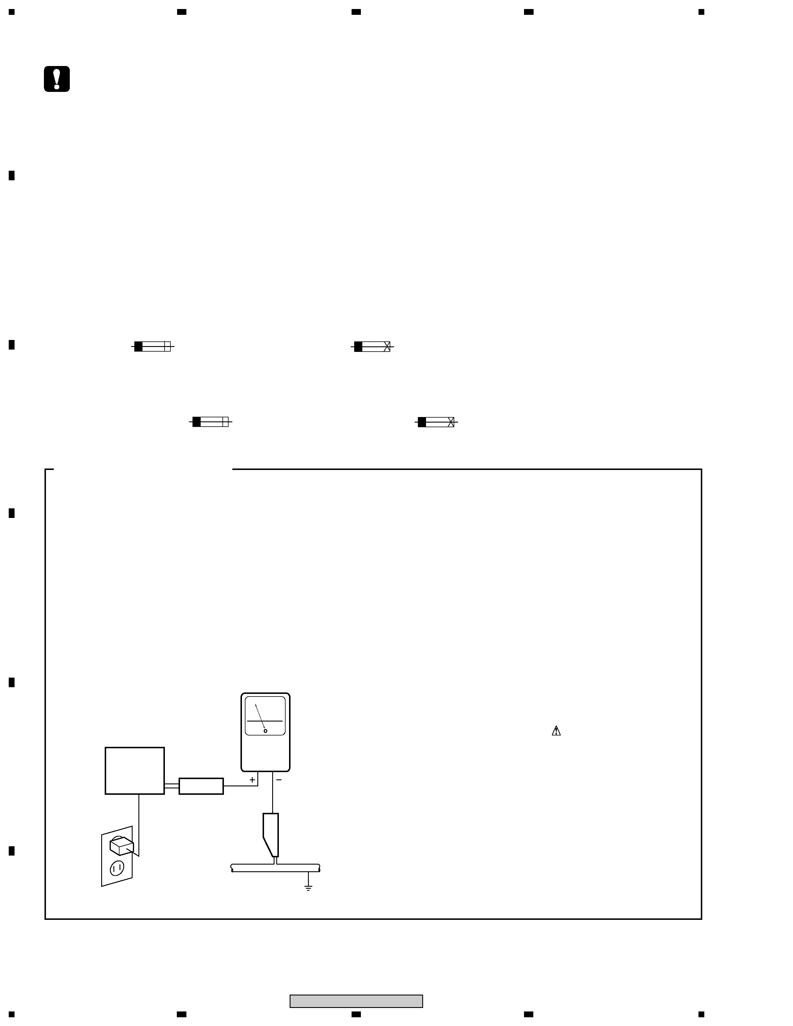
SAFETY INFORMATION ...................................................................................................................................... 2
1. SPECIFICATIONS ............................................................................................................................................ 5
2. EXPLODED VIEWS AND PARTS LIST .......................................................................................................... 6
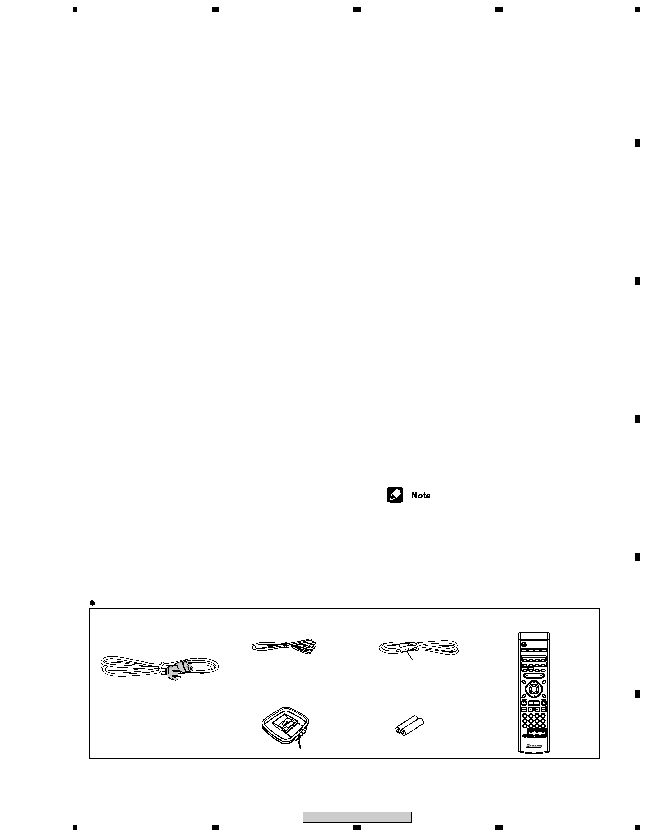
2.1 PACKING .................................................................................................................................................... 6
2.2 EXTERIOR SECTION ............................................................................................................................... 8
2.3 FRONT SECTION ................................................................................................................................... 10
2.4 LOADING MECANISM ASSY ................................................................................................................. 12
2.5 TRAVERSE MECHANISM ASSY ........................................................................................................... 14
3. BLOCK DIAGRAM AND SCHEMATIC DIAGRAM ........................................................................................ 16
3.1 BLOCK DIAGRAM ................................................................................................................................... 16
3.2 LOAB ASSY and OVERALL WIRING DIAGRAM ................................................................................... 18
3.3 DVDM ASSY 1/2 ..................................................................................................................................... 20
3.4 DVDM ASSY 2/2 ..................................................................................................................................... 22
3.5 DVD IF ASSY .......................................................................................................................................... 24
3.6 DSP ASSY ............................................................................................................................................... 26
3.7 FM/AM TUNER MODULE ....................................................................................................................... 28
3.8 AMP ASSY .............................................................................................................................................. 30
3.9 CONTROL ASSY 1/3, TRADE2 and TRADE3 ASSYS .......................................................................... 32
3.10 CONTROL ASSY 2/3 for XV-DV820 ..................................................................................................... 34
3.11 CONTROL ASSY 2/3 for XV-DV620 ..................................................................................................... 36
3.12 CONTROL ASSY 3/3 ............................................................................................................................ 38
3.13 POWER ASSY 1/2 ................................................................................................................................ 40
3.14 POWER ASSY 2/2 and TRADE1 ASSY ............................................................................................... 42
3.15 DISPLAY and HP ASSYS ..................................................................................................................... 44
3.16 WAVEFORMS ....................................................................................................................................... 46
4. PCB CONNECTION DIAGRAM ..................................................................................................................... 47
4.1 LOAB ASSY ............................................................................................................................................ 47
4.2 DVDM ASSY ........................................................................................................................................... 48
4.3 DVD IF ASSY .......................................................................................................................................... 52
4.4 DSP ASSY ............................................................................................................................................... 54
4.5 FM/AM TUNER MODULE ....................................................................................................................... 56
4.6 DISPLAY and HP ASSYS ....................................................................................................................... 57
4.7 AMP ASSY .............................................................................................................................................. 58
4.8 CONTROL, TRADE2 and TRADE3 ASSYS ........................................................................................... 60
4.9 POWER and TRADE1 ASSYS ............................................................................................................... 64
5. PCB PARTS LIST .......................................................................................................................................... 68
6. ADJUSTMENT ............................................................................................................................................... 75
7. GENERAL INFORMATION ............................................................................................................................ 81
7.1 DIAGNOSIS ............................................................................................................................................. 81
7.1.1 TEST MODE .................................................................................................................................... 81
7.1.2 DISPLAY OF THE MECHANISM ERROR HISTORY ..................................................................... 87
7.1.3 TROUBLE SHOOTING .................................................................................................................... 90
7.1.4 SEQUENCE AFTER POWER ON ...................................................................................................92
7.1.5 PROTECTION CIRCUIT .................................................................................................................. 95
7.1.6 DISASSEMBLY ................................................................................................................................ 97
7.2 IC ........................................................................................................................................................... 102
7.3 CLEANING ............................................................................................................................................ 121
8. PANEL FACILITIES ..................................................................................................................................... 122
background image
5
1
23
4
1
2
3
4
C
D
F
A
B
E
XV-DV820, XV-DV620
Accessories
· Power cord
(XDG3007)
· FM Antenna
(ADH7028)
· AM Loop Antenna
(ATB7009)
· Video Cord
(L = 1.5m)(VDE1053)
· Remote Control Unit
(AXD7337)
· Dry Cell Battery
(R6P, AA)
Yellow
5
46
3
8
79
0
2
1
TEST TONE
PROGRAM
FOLDER
FOLDER
CH LEVEL
TIMER
DVD DISP
INPUT
SHIFT
CHANEL
VOLUME
DIMMER
TV CONTROL
REPEAT
RANDOM
CLEAR
ENTER
5.1ch DVD SURROUND SYSTEM
AXD7337
DVD
AUDIO SUBTITLE ANGLE
ZOOM
AUTO SURROUND ADVANCED
QUIET/
MIDNIGHT
TV
LINE
L1/L2
FM/AM
DVD/CD
STANDBY/ON
BASSMODE SYSTEMDISP MUTE
ROOM
SETUP
SYSTEM SETUP
DVD SETUP
TOP MENU
DVD MENU
RETURN
SOUND
MODE
ST
ST
TUNE
TUNE
VOLUME
ENTER
1. SPECIFICATIONS
Amplifier section
Continuous Power Output (RMS):
Front, center, surround ... 75 W per channel
(1 kHz, 10 % T.H.D., 6
)
Subwoofer75 W (100 Hz, 10 % T.H.D., 6
)
Continuous Power Output :
Front, center, surround ... 62 W per channel
(1 kHz, 1 % T.H.D., 6
)
Subwoofer . 62 W (100 Hz, 1 % T.H.D., 6
)
Disc section
Digital audio
characteristics ............. DVD fs: 96 kHz, 24-bit
Type ........ DVD system, video CD system and
compact disc digital audio system
Frequency response ............... 4 Hz to 44 kHz
FM tuner section
Frequency range .................... 87.5 ­ 108 MHz
Antenna ............................... 75
, unbalanced
AM tuner section
Frequency range
With 10 kHz step ...... 530 kHz to 1,700 kHz
Antenna ..................................... Loop antenna
Miscellaneous
Power requirements
U.S. model
AC 120V, 60Hz
Power consumption
U.S. model ...............................
...............
215 W
Power consumption in standby
U.S. model .............................. 0.38 W
Dimensions ... 360 (W) x 70 (H) x 393 (D) mm/
14-3/16 (W) x 2-3/4 (H) x 15-1/2 (D) in.
Weight ................................... 7.0 kg/15 lb 7 oz
Accessories (DVD/CD receiver)
Remote control ............................................. 1
AA/R6P dry cell batteries .............................. 2
Video cable (yellow plugs) ............................ 1
AM loop antenna ........................................... 1
FM antenna .................................................. 1
Power cord .................................................... 1
Warranty Card ............................................... 1
Operating instructions
Quick setup guide
Speaker System
Front and surround speakers
Enclosure .............. Closed-box bookshelf type
(magnetically shielded)
System .......................... 8.7 cm 1-way system
Speakers .............................. 8.7 cm cone type
Nominal impedance .................................. 6
Frequency range ................. 100 Hz to 20 kHz
Maximum Input Power ............................ 75 W
Dimensions ... 110 (W) x 155 (H) x 76 (D) mm/
4-5/16 (W) x 6-1/8 (H) x 3 (D) in.
Weight ................................. 0.75 kg/1 lb 10 oz
Center speaker
Enclosure .............. Closed-box bookshelf type
(magnetically shielded)
System .......................... 8.7 cm 1-way system
Speakers .............................. 8.7 cm cone type
Nominal impedance .................................. 6
Frequency range ................. 100 Hz to 20 kHz
Maximum Input Power ............................ 75 W
Dimensions ... 200 (W) x 110 (H) x 76 (D) mm/
7-7/8 (W) x 4-5/16 (H) x 3 (D) in.
Weight ................................... 0.8 kg/1 lb 12 oz
Subwoofer
Enclosure ...................... Bass-reflex floor type
(magnetically shielded)
System ........................... 16 cm 1-way system
Speaker ................................. 16 cm cone type
Nominal impedance .................................. 6
Frequency range .................. 30 Hz to 2.8 kHz
Maximum Input Power ............................ 75 W
Dimensions . 130 (W) x 360 (H) x 360 (D) mm/
5-1/8 (W) x 14-3/16 (H) x 14-3/16 (D) in.
Weight ................................... 4.0 kg/8 lb 13 oz
Accessories (Speaker system)
Speaker cords ............................................... 6
Non-slip pads .............................................. 24
· Specifications and design subject to
possible modification without notice,
due to improvements.

Reviews

There are no reviews of this manual yet.