XV-DV370
4
12
34
1
234
C
D
F
A
B
E
CONTENTS
SAFETY INFORMATION..................................................................................................................................... 2
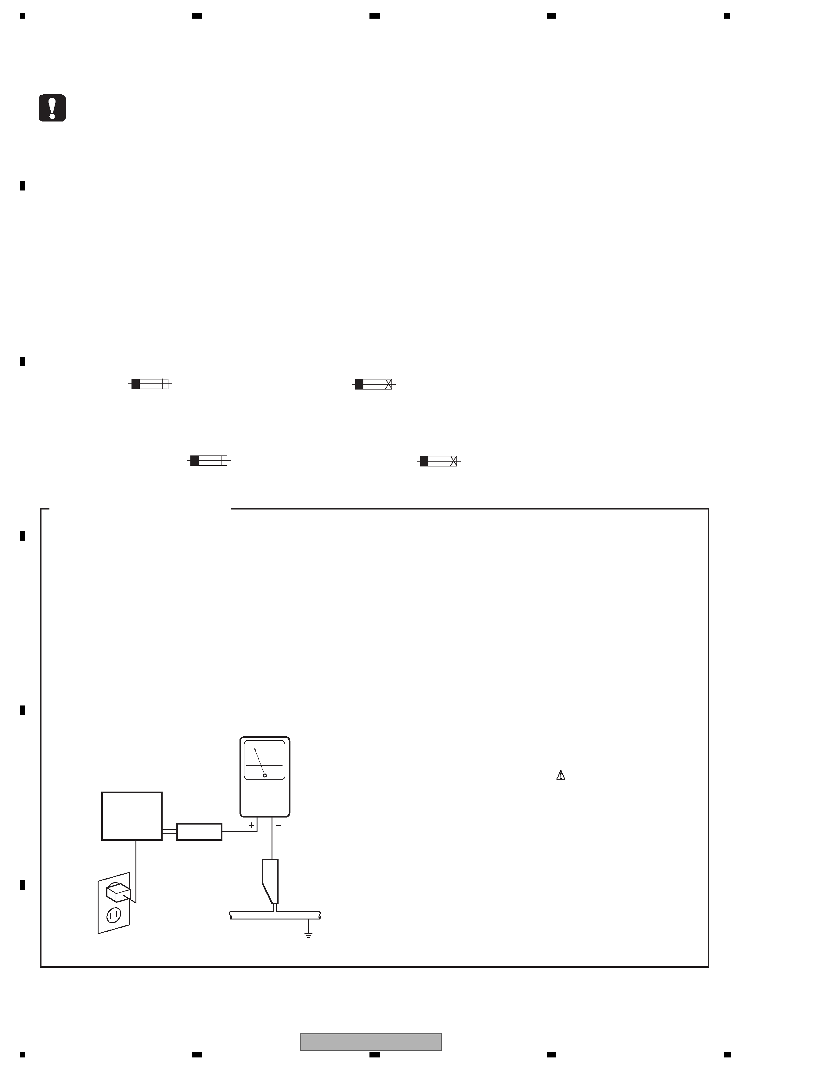
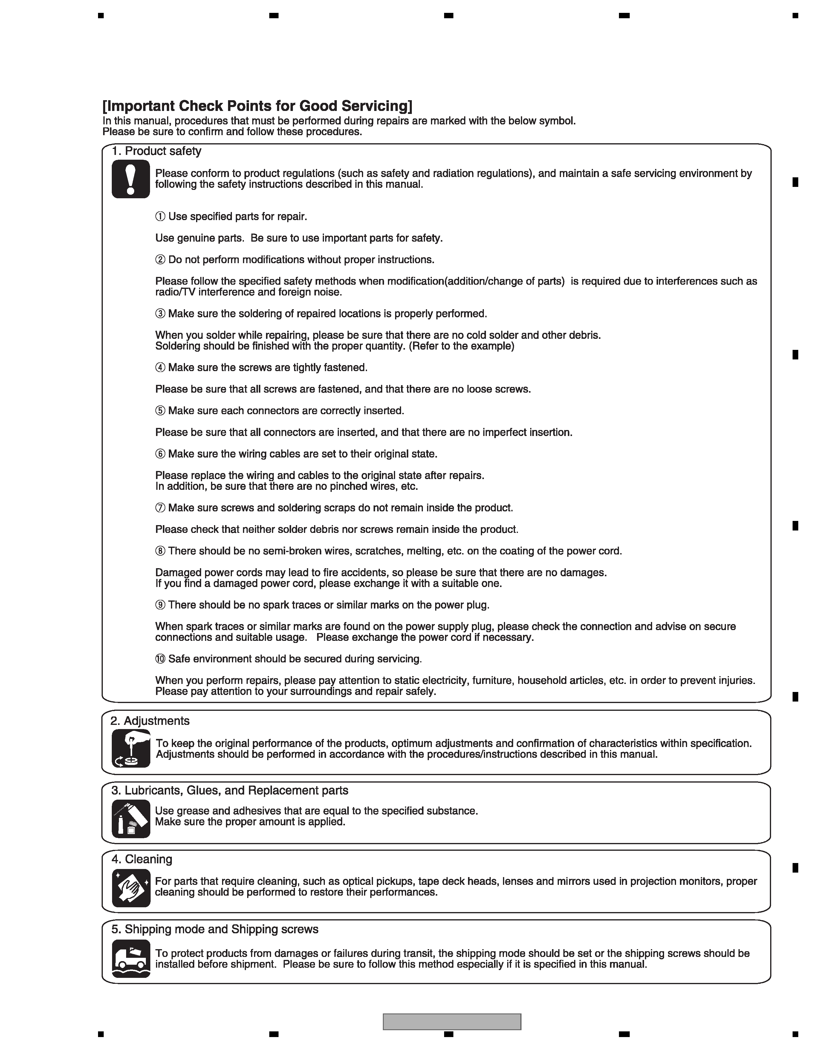
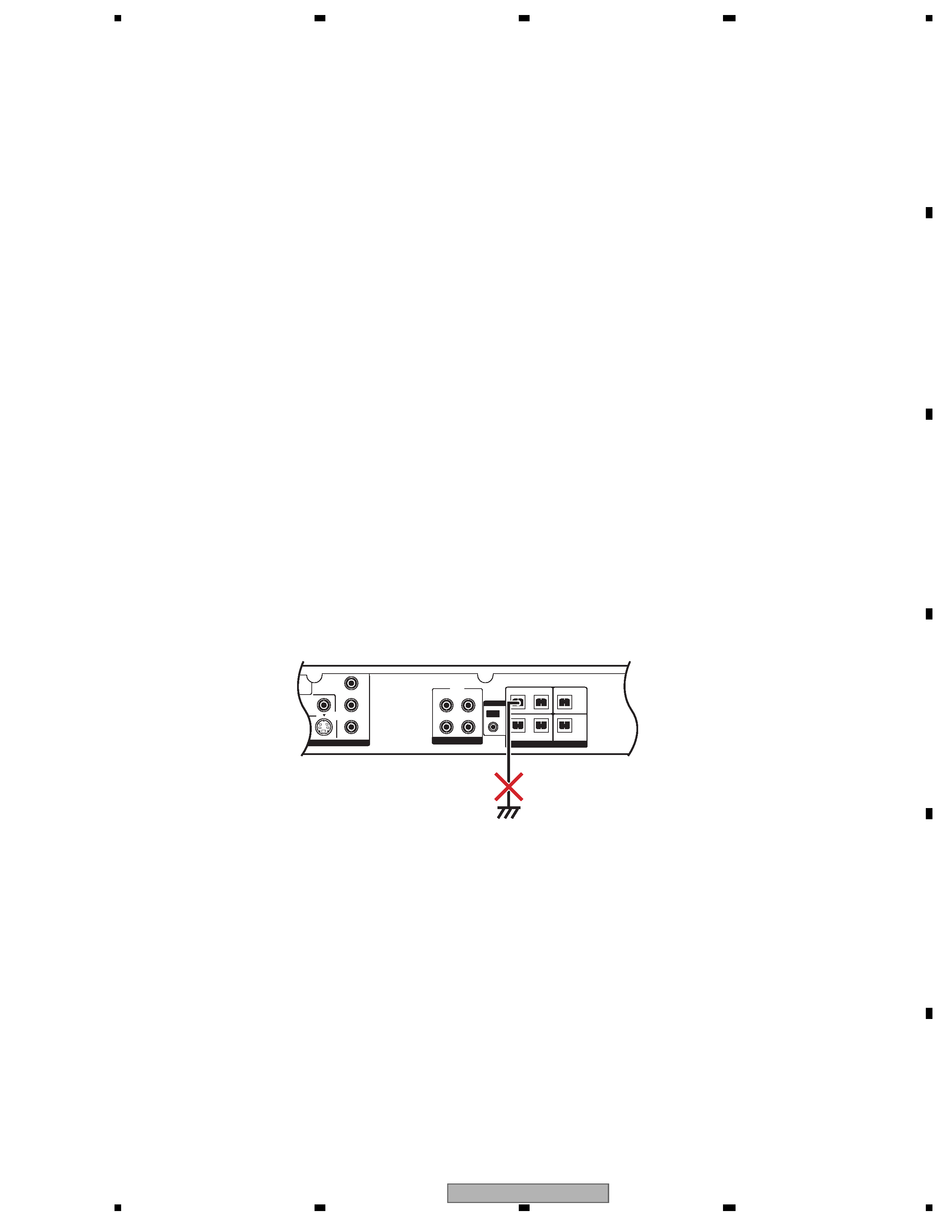
1. SERVICE PRECAUTIONS ............................................................................................................................... 5
1.1 NOTES ON SOLDERING .......................................................................................................................... 5
1.2 CAUTION................................................................................................................................................... 5
2. SPECIFICATIONS............................................................................................................................................ 6
2.1 SPECIFICATIONS and ACCESORRIES ................................................................................................... 6
2.2 PANEL FACILITIES.................................................................................................................................... 7
3. BASIC ITEMS FOR SERVICE........................................................................................................................ 10
3.1 CHECK POINTS AFTER SERVICING..................................................................................................... 10
3.2 PCB LOCATIONS .....................................................................................................................................11
3.3 JIGS LIST ................................................................................................................................................ 12
3.4 CLEANING............................................................................................................................................... 12
4. BLOCK DIAGRAM.......................................................................................................................................... 14
4.1 OVERALL WIRING CONNECTION DIAGRAM and LOAB ASSY ........................................................... 14
4.2 OVERALL BLOCK DIAGRAM.................................................................................................................. 16
5. DIAGNOSIS.................................................................................................................................................... 18
5.1 METHOD FOR DIAGNOSING DEGRADATION OF THE LDS ON THE PICKUP................................... 18
5.2 DVD TROUBLE SHOOTING ................................................................................................................... 19
5.3 CIRCUIT DESCRIPTION OF DIGITAL AMP. SECTION .......................................................................... 22
5.4 SPECIFICATIONS FOR THE PROTECTION CIRCUITS FOR THE DIGITAL AMPLIFIER..................... 23
5.5 PASS/FAIL TEST PROCEDURE OF HDMI TRANSMITTER IC.............................................................. 24
6. SERVICE MODE ............................................................................................................................................ 25
6.1 TEST MODE ............................................................................................................................................ 25
6.2 DISPLAY SPECIFICATION OF THE TEST MODE.................................................................................. 26
6.3 FUNCTIONAL SPECIFICATION OF THE SHORTCUT KEY .................................................................. 27
6.4 SPECIFICATION OF MODEL INFORMATION DISPLAY ........................................................................ 28
6.5 FUNCTIONAL SPECIFICATION OF THE SERVICE MODE ................................................................... 29
6.6 SERVICE TEST MODE ........................................................................................................................... 30
7. DISASSEMBLY .............................................................................................................................................. 33
8. EACH SETTING AND ADJUSTMENT ........................................................................................................... 40
8.1 ADJUSTMENT......................................................................................................................................... 40
8.2 ID NUMBER AND ID DATA SETTING ..................................................................................................... 45
9. EXPLODED VIEWS AND PARTS LIST.......................................................................................................... 48
9.1 PACKING SECTION ................................................................................................................................ 48
9.2 EXTERIOR SECTION.............................................................................................................................. 50
9.3 06 LOADER ASSY................................................................................................................................... 52
9.4 TRAVERSE MECHANISM ASSY-S ......................................................................................................... 54
10. SCHEMATIC DIAGRAM............................................................................................................................... 56
10.1 DVD MAIN ASSY (1/5) .......................................................................................................................... 56
10.2 DVD MAIN ASSY (2/5) .......................................................................................................................... 58
10.3 DVD MAIN ASSY (3/5) .......................................................................................................................... 60
10.4 DVD MAIN ASSY (4/5) .......................................................................................................................... 62
10.5 DVD MAIN ASSY (5/5) .......................................................................................................................... 64
10.6 DAMP ASSY (1/2).................................................................................................................................. 66
10.7 DAMP ASSY (2/2).................................................................................................................................. 68
10.8 DISPLAY, USB, LED and KEY ASSYS .................................................................................................. 70
10.9 POWER SUPPLY UNIT ......................................................................................................................... 72
10.10 WAVEFORMS...................................................................................................................................... 74
11. PCB CONNECTION DIAGRAM.................................................................................................................... 77
11.1 LOAB ASSY ........................................................................................................................................... 77
11.2 DVD MAIN ASSY ................................................................................................................................... 78
11.3 DAMP ASSY .......................................................................................................................................... 82
11.4 DISPLAY, USB, LED and KEY ASSYS .................................................................................................. 84
11.5 POWER SUPPLY UNIT ......................................................................................................................... 86
12. PCB PARTS LIST ......................................................................................................................................... 88