PIONEER XV-DV424/NTXJN Service Manual

Cover page of PIONEER XV-DV424/NTXJN Service Manual

Service Manual for PIONEER XV-DV424/NTXJN, downloadable as a PDF file.

We also have owner's manual to this model.

Manual details

  • Immediate download after payment.
  • Delivered as a PDF file.
  • The manual has 124 pages
  • File size: 9.15 MB
  • Available language versions: English
  • Different language versions may vary sligthly in file size and page count.

We guarantee that...

  • our manuals are complete,
  • the manual includes circuit diagrams,
  • our manuals are checked with antivirus,
  • We'll issue refund if the manual is damaged, incomplete or unreadable (our refund policy)

Sample pages

Thumbnail of page 1Thumbnail of page 2Thumbnail of page 3Thumbnail of page 4
Thumbnail of page 5Thumbnail of page 6Thumbnail of page 7Thumbnail of page 8
Thumbnail of page 9
background image
ORDER NO.
PIONEER CORPORATION 4-1, Meguro 1-chome, Meguro-ku, Tokyo 153-8654, Japan
PIONEER ELECTRONICS (USA) INC. P.O. Box 1760, Long Beach, CA 90801-1760, U.S.A.
PIONEER EUROPE NV Haven 1087, Keetberglaan 1, 9120 Melsele, Belgium
PIONEER ELECTRONICS ASIACENTRE PTE. LTD. 253 Alexandra Road, #04-01, Singapore 159936
PIONEER CORPORATION 2004
PHONES
6 DVD/CD
0 OPEN/CLOSE
FM/AM
VOL.
­ DOWN
UP +
7
STANDBY/ON
XV-DV740
RRV2946
DVD/CD RECEIVER
XV-DV740
XV-DV440
THIS MANUAL IS APPLICABLE TO THE FOLLOWING MODEL(S) AND TYPE(S).
Model
Type
Power Requirement
Regional restriction
codes (Region No.)
Remarks
XV-DV740
KUCXJ
AC120V
XV-DV440
KCXJ
AC120V
For details, refer to "Important symbols for good services".
T-ZZK MAY 2004 printed in Japan
background image
XV-DV740
2
12
34
12
3
4
C
D
F
A
B
E
SAFETY INFORMATION
This service manual is intended for qualified service technicians; it is not meant for the casual
do-it-yourselfer. Qualified technicians have the necessary test equipment and tools, and have been
trained to properly and safely repair complex products such as those covered by this manual.
Improperly performed repairs can adversely affect the safety and reliability of the product and may
void the warranty. If you are not qualified to perform the repair of this product properly and safely, you
should not risk trying to do so and refer the repair to a qualified service technician.
WARNING
This product contains lead in solder and cer tain electrical par ts contain chemicals which are known to the state of California to
cause cancer, bir th defects or other reproductive harm.
Health & Safety Code Section 25249.6 ­ Proposition 65
NOTICE
(FOR CANADIAN MODEL ONLY)
Fuse symbols
(fast operating fuse)
and/or
(slow operating fuse) on PCB indicate that replacement
parts must be of identical designation.
REMARQUE
(POUR MODÈLE CANADIEN SEULEMENT)
Les symboles de fusible
(fusible de type rapide)
et/ou
(fusible de type lent) sur CCI indiquent que
les pièces de remplacement doivent avoir la même désignation.
ANY MEASUREMENTS NOT WITHIN THE
LIMITS OUTLINED ABOVE ARE INDICATIVE
OF A POTENTIAL SHOCK HAZARD AND
MUST BE CORRECTED BEFORE RETURN-
ING THE APPLIANCE TO THE CUSTOMER.
2. PRODUCT SAFETY NOTICE
Many electrical and mechanical parts in the appliance
have special safety related character istics. These are
often not evident
from visual
inspection nor the
protection afforded by them necessarily can be obtained
by using replacement components rated for voltage,
wattage, etc. Replacement par ts which have these
special safety character istics are identified in this
Service Manual.
Electr ical components having such features are
identified by marking with a
on the schematics and
on the parts list in this Service Manual.
The use of a substitute replacement component which
does not have the same safety characteristics as the
PIONEER recommended replacement one, shown in the
parts list in this Service Manual, may create shock, fire,
or other hazards.
Product Safety is continuously under review and new
instructions are issued from time to time. For the latest
infor mation, always consult the current PIONEER
Ser vice Manual. A subscription to, or
additional copies
of, PIONEER Ser vice Manual may be obtained at a
nominal charge from PIONEER.
(FOR USA MODEL ONLY)
1. SAFETY PRECAUTIONS
The following check should be perfor med for the
continued protection of the customer and ser vice
technician.
LEAKAGE CURRENT CHECK
Measure leakage current to a known ear th ground
(water pipe, conduit, etc.) by connecting a leakage
current tester such as Simpson Model 229-2 or
equivalent between the ear th ground and all exposed
metal par ts of the appliance (input/output ter minals,
screwheads, metal overlays, control shaft, etc.). Plug
the AC line cord of the appliance directly into a 120V
AC 60 Hz outlet and turn the AC power switch on. Any
current measured must not exceed 0.5 mA.
Device
under
test
Leakage
current
tester
Earth
ground
Reading should
not be above
0.5 mA
Also test with
plug reversed
(Using AC adapter
plug as required)
Test all
exposed metal
surfaces
AC Leakage Test
background image
XV-DV740
3
56
78
56
7
8
C
D
F
A
B
E
[ Important symbols for good services ]
In this manual, the symbols shown-below indicate that adjustments, settings or cleaning should be made securely.
When you find the procedures bearing any of the symbols, be sure to fulfill them:
2. Adjustments
To keep the original performances of the product, optimum adjustments or specification confirmation is indispensable.
In accordance with the procedures or instructions described in this manual, adjustments should be performed.
3. Cleaning
For optical pickups, tape-deck heads, lenses and mirrors used in projection monitors, and other parts requiring cleaning,
proper cleaning should be performed to restore their performances.
5. Lubricants, glues, and replacement parts
Appropriately applying grease or glue can maintain the product performances. But improper lubrication or applying
glue may lead to failures or troubles in the product. By following the instructions in this manual, be sure to apply the
prescribed grease or glue to proper portions by the appropriate amount.For replacement parts or tools, the prescribed
ones should be used.
4. Shipping mode and shipping screws
To protect the product from damages or failures that may be caused during transit, the shipping mode should be set or
the shipping screws should be installed before shipping out in accordance with this manual, if necessary.
1. Product safety
You should conform to the regulations governing the product (safety, radio and noise, and other regulations), and
should keep the safety during servicing by following the safety instructions described in this manual.
Disc / content format playback
compatibility
This player is compatible with a wide range of
disc types (media) and formats. Playable discs
will generally feature one of the following logos
on the disc and/or disc packaging. Note
however that some disc types, such as
recordable CD and DVD, may be in an
unplayable format­­see below for further
compatibility information.
·
·
is a trademark of Fuji Photo Film Co. Ltd.
Also compatible with KODAK Picture CD
This player supports the IEC's Super VCD stan-
dard for superior picture quality, dual
soundtracks, and widescreen support.
DVD-Video
DVD-R
DVD-RW
Video CD
Fujicolor CD
Audio CD
CD-R
CD-RW
VIDEO
CD
Super Video CD (Super VCD)
background image
XV-DV740
4
12
34
12
3
4
C
D
F
A
B
E
CONTENTS
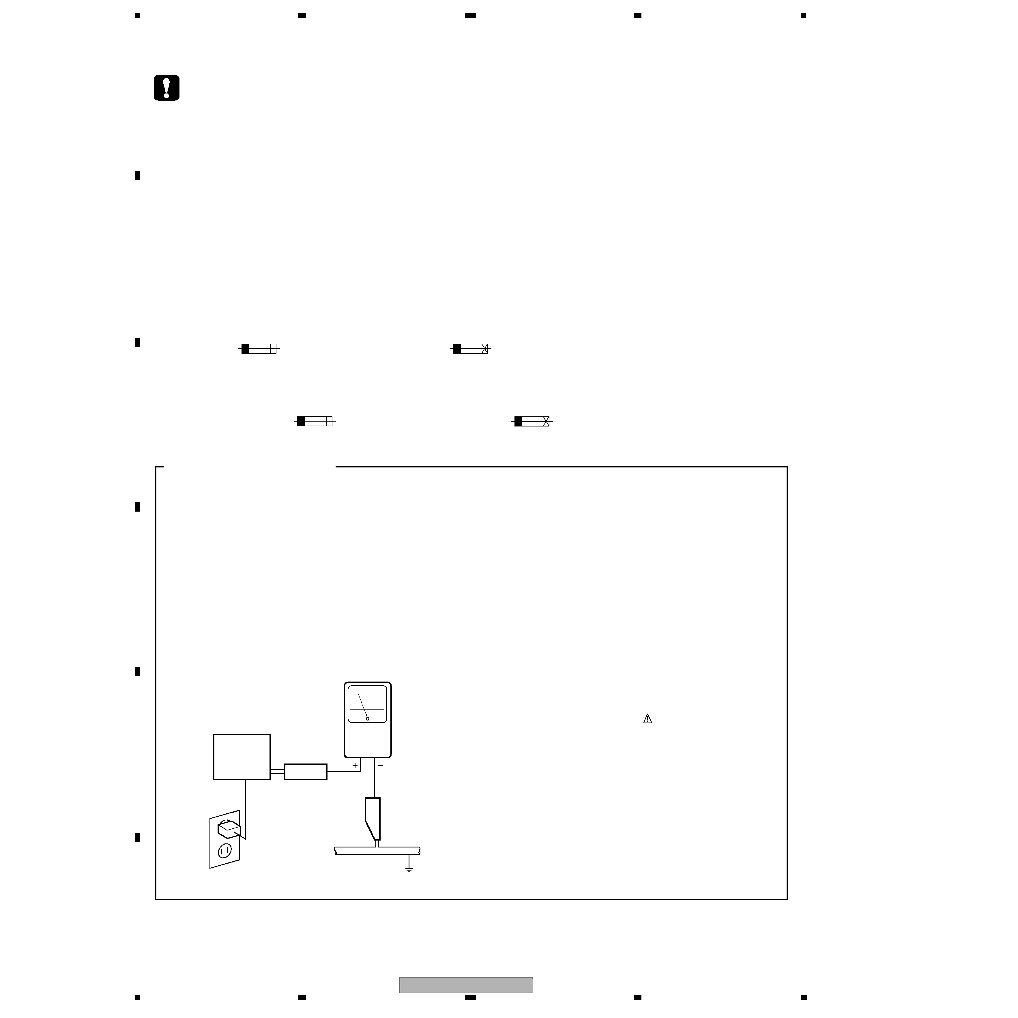
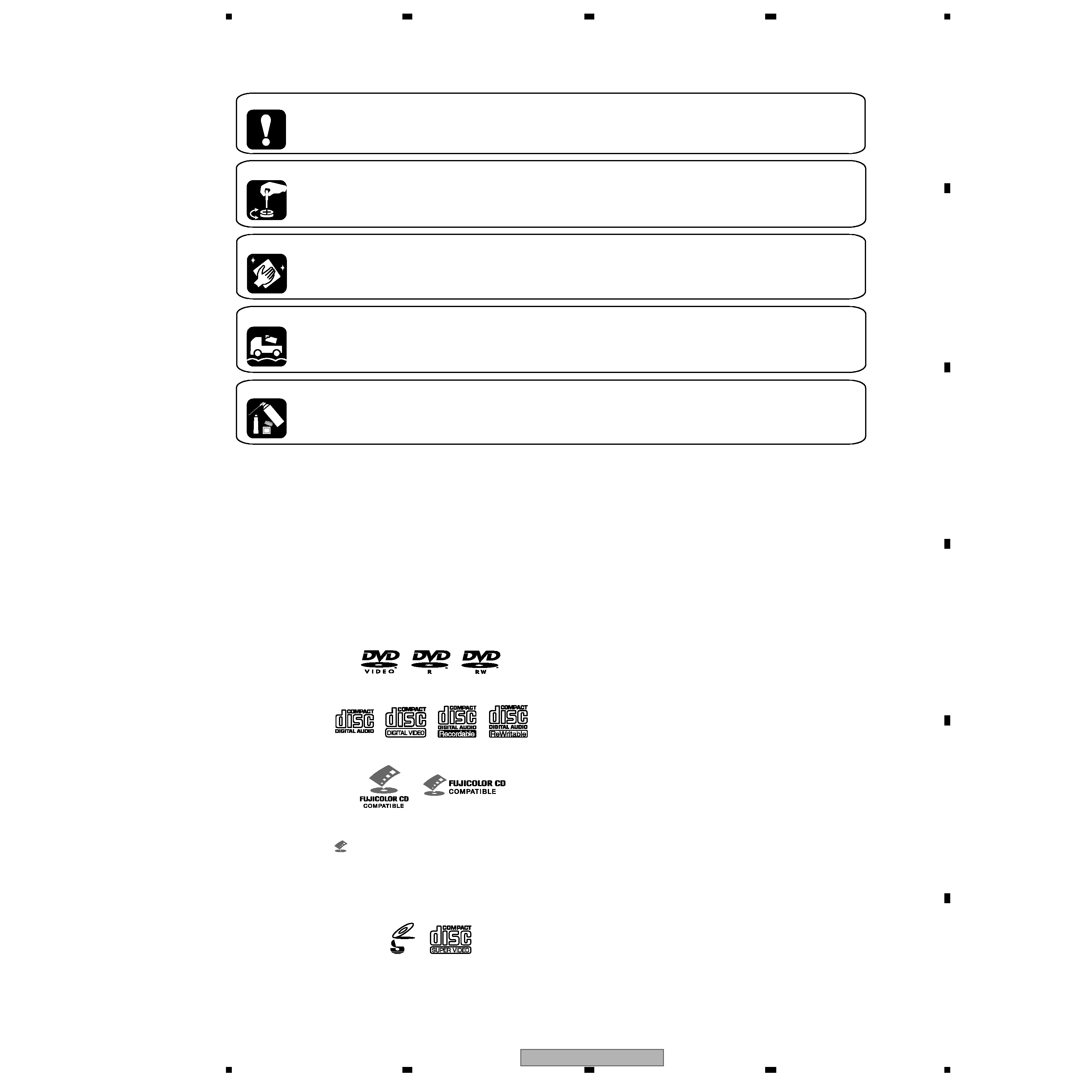
SAFETY INFORMATION ..................................................................................................................................... 2
1. SPECIFICATIONS ............................................................................................................................................ 5
2. EXPLODED VIEWS AND PARTS LIST ............................................................................................................ 6
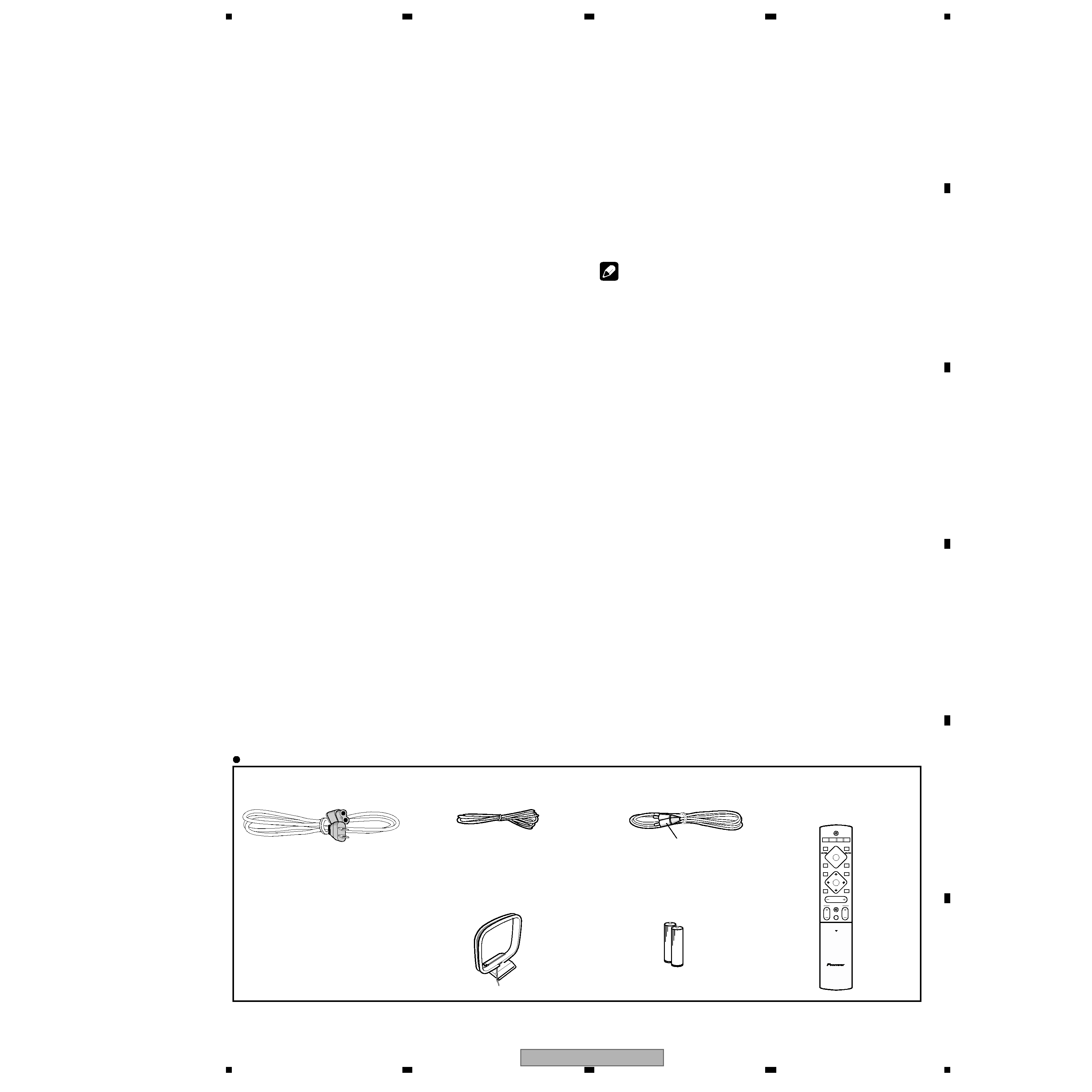
2.1 PACKING ................................................................................................................................................... 6
2.2 EXTERIOR SECTION................................................................................................................................ 8
2.3 FRONT PANEL SECTION ....................................................................................................................... 10
2.4 01 LOADER ASSY................................................................................................................................... 12
2.5 TRAVERSE MECHA ASSY-S .................................................................................................................. 14
3. BLOCK DIAGRAM AND SCHEMATIC DIAGRAM ..........................................................................................16
3.1 BLOCK DIAGRAM ................................................................................................................................... 16
3.2 LOAB ASSY and OVERALL WIRING DIAGRAM..................................................................................... 18
3.3 DVDM ASSY(1/3)..................................................................................................................................... 20
3.4 DVDM ASSY(2/3)..................................................................................................................................... 22
3.5 DVDM ASSY(3/3)..................................................................................................................................... 24
3.6 DSP ASSY (1/2)....................................................................................................................................... 26
3.7 DSP ASSY (2/2)....................................................................................................................................... 28
3.8 6CH AMP ASSY ...................................................................................................................................... 30
3.9 CONTROL(1/4), TRADE3 and TRADE2 ASSYS ..................................................................................... 32
3.10 CONTROL ASSY(2/4)............................................................................................................................ 34
3.11 CONTROL ASSY(3/4)............................................................................................................................ 36
3.12 CONTROL ASSY(4/4) and HP ASSYS.................................................................................................. 38
3.13 POWER ASSY(1/2)................................................................................................................................ 40
3.14 POWER ASSY(2/2) and TRADE1 ASSYS............................................................................................. 42
3.15 VIDEO ASSY ......................................................................................................................................... 44
3.16 DISPALY ASSY ...................................................................................................................................... 46
3.17 WAVEFORMS ........................................................................................................................................ 48
4. PCB CONNECTION DIAGRAM ..................................................................................................................... 49
4.1 LOAB ASSY ............................................................................................................................................. 49
4.2 DVDM ASSY ............................................................................................................................................ 50
4.3 DSP ASSY ............................................................................................................................................... 52
4.4 6CH AMP ASSY ...................................................................................................................................... 54
4.5 CONTROL ASSY ..................................................................................................................................... 56
4.6 TRADE2,TRADE3 and HP ASSYS .......................................................................................................... 60
4.7 POWER ASSY ......................................................................................................................................... 62
4.8 TRADE1, VIDEO and DISPLAY ASSYS .................................................................................................. 66
5. PCB PARTS LIST ........................................................................................................................................... 70
6. ADJUSTMENT ............................................................................................................................................... 76
6.1 ADJUSTMENT ITEMS AND LOCATION ................................................................................................. 76
6.2 JIGS AND MEASURING INSTRUMENTS ............................................................................................... 76
6.3 NECESSARY ADJUSTMENT POINTS ................................................................................................... 77
6.4 TEST MODE ............................................................................................................................................ 78
6.5 MECHANISM ADJUSTMENT .................................................................................................................. 79
7. GENERAL INFORMATION ............................................................................................................................. 81
7.1 DIAGNOSIS ............................................................................................................................................. 81
7.1.1 TEST MODE ......................................................................................................................................... 81
7.1.2 DISPLAY SPECIFICATIONS OF THE TEST MODE ............................................................................. 83
7.1.3 FUNCTIONAL SPECIFICATION OF THE SHORTCUT KEY ................................................................ 84
7.1.4 SPECIFICATION OF MODEL INFORMATION DISPLAY...................................................................... 85
7.1.5 FUNCTIONAL SPECIFICATION OF THE SERVICE MODE................................................................. 86
7.1.6 MECHANICAL ERROR HISTORY ........................................................................................................ 87
7.1.7 ID NUMBER AND DATA SETTING ....................................................................................................... 92
7.1.8 METHOD FOR DIAGNOSING DEGRADATION OF THE LDS ON THE PICKUP ASSY...................... 95
7.1.9 TROUBLE SHOOTING ......................................................................................................................... 96
7.1.10 DSP TROUBLE SHOOTING ............................................................................................................... 99
7.1.11 DISASSEMBLY ................................................................................................................................. 101
7.2 IC ........................................................................................................................................................... 110
7.3 EXPLANATION ...................................................................................................................................... 113
7.3.1 SEQUENCE AFTER POWER ON ...................................................................................................... 113
7.3.2 PROTECTION CIRCUIT ..................................................................................................................... 114
7.4 CLEANING............................................................................................................................................. 118
8. PANEL FACILITIES ...................................................................................................................................... 119
background image
XV-DV740
5
56
78
56
7
8
C
D
F
A
B
E
1. SPECIFICATIONS
Amplifier section
Continuous Power Output (RMS):
Front, Center, Surround . .
100 W per channel
(1 kHz, 10 % T.H.D., 6
)
Subwoofer . . 100 W (100 Hz, 10 % T.H.D., 6
)
Continuous Power Output:
Front, Center, Surround . . .
75 W per channel
(1 kHz, 1 % T.H.D., 6
)
Subwoofer . . . . 75 W (100 Hz, 1 % T.H.D., 6
)
Disc section
Digital audio
characteristics . . . . . . . . . DVD fs: 96 kHz, 24-bit
Type . . . . . . . DVD system, video CD system and
compact disc digital audio system
Total harmonic distortion. . . . . . . . . . . . .
0.004%
Frequency
response . . . .4 Hz to 44 kHz (96kHz sampling) /
4 Hz to 22 kHz (48kHz sampling)
Wow and Flutter . . . . . . . .Limit of measurement
(
±0.001 % W.PEAK) or less (JEITA)
FM tuner section
Frequency range. . . . . . . . . . . . . 87.5 ­ 108 MHz
Antenna . . . . . . . . . . . . . . . . . . 75
, unbalanced
AM tuner section
Frequency range
With 9kHz step . . . . . . . . 531 kHz to 1,602 kHz
With 10kHz step . . . . . . . 530 kHz to 1,700 kHz
Antenna . . . . . . . . . . . . . . . . . . . . . . Loop antenna
Miscellaneous
Power requirements. . . . . . . . . . AC 120 V, 60 Hz
Power consumption . . . . . . . . . . . . . . . . . . . 175W
Power consumption in standby. . . . . . . . . . 0.5 W
Dimensions . . . . . 420 (W) x 70 (H) x 396 (D) mm
16 9/16 (W) x 213/16 (H) x 155/8 (D) in.
Weight . . . . . . . . . . . . . . . . . . . 7.0 kg / 15 lb. 7 oz
Accessories (DVD/CD receiver)
Remote control . . . . . . . . . . . . . . . . . . . . . . . . . 1
AA/R6 d ry cell batteries. . . . . . . . . . . . . . . . . . . . 2
Video cable (yellow plugs). . . . . . . . . . . . . . . . . . 1
AM loop antenna . . . . . . . . . . . . . . . . . . . . . . . . . 1
FM antenna . . . . . . . . . . . . . . . . . . . . . . . . . . . . 1
Power cord . . . . . . . . . . . . . . . . . . . . . . . . . . . . . .1
Setup Guide . . . . . . . . . . . . . . . . . . . . . . . . . . . . .1
Operating instructions . . . . . . . . . . . . . . . . . . . . . 1
Warranty Card . . . . . . . . . . . . . . . . . . . . . . . . . . . 1
Note
· Specifications and design subject to
possible modification without notice, due
to improvements.
ST+
TUNE+
ENTER
TUNE­
MASTER
VOLUME
ST­
STANDBY/ON
CD
FM/AM
OPEN CLOSE
DISPLAY
DVD
TUNER
TV
LINE
L1/L2
DVD MENU
RETURN
SOUND
TV CONTROL
CH
VOL
INPUT
OPEN
MUTE
Accessories
· Power cord
(ADG7021)
· FM Antenna
(ADH7030)
· AM Loop Antenna
(ATB7013)
· Video Cord
(L = 1.5m)(XDE3046)
· Remote Control Unit
(XXD3076)
· Dry Cell Battery
(R6P, AA)
Yellow
Manufactured under license from Dolby
Laboratories. "Dolby", "Pro Logic" and the double-D
symbol are trademarks of Dolby Laboratories.
"DTS" and "DTS Digital Surround" are registered
trademarks of Digital Theater Systems, Inc.

Reviews

There are no reviews of this manual yet.