PIONEER CORPORATION 4-1, Meguro 1-chome, Meguro-ku, Tokyo 153-8654, Japan
PIONEER ELECTRONICS SERVICE, INC. P.O. Box 1760, Long Beach, CA 90801-1760, U.S.A.
PIONEER EUROPE NV Haven 1087, Keetberglaan 1, 9120 Melsele, Belgium
PIONEER ELECTRONICS ASIACENTRE PTE. LTD. 253 Alexandra Road, #04-01, Singapore 159936
PIONEER CORPORATION 2001
c
ORDER NO.
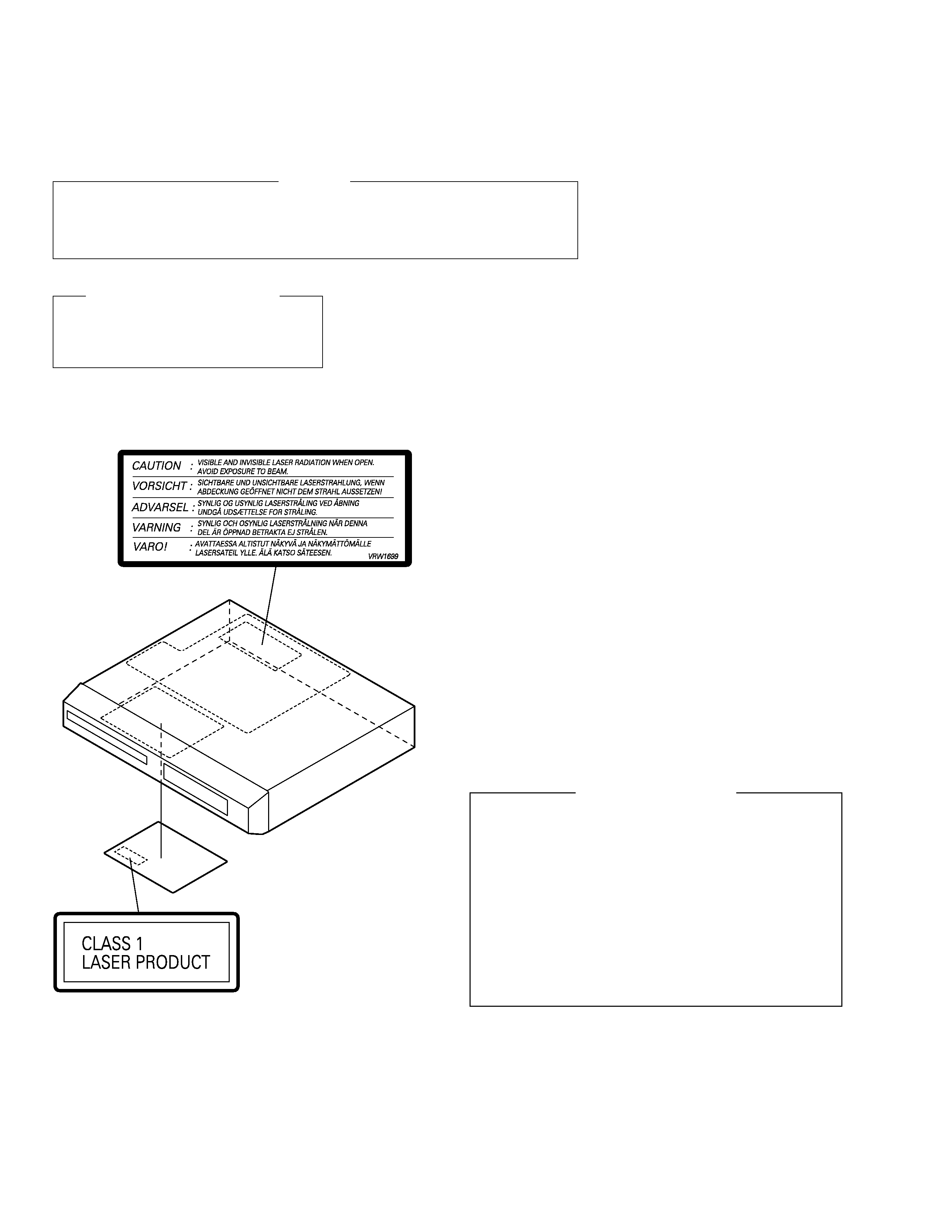
XV-S100DV
RRV2497
T IZK AUG. 2001 Printed in Japan
Type
Model
Power Requirement
Region No.
Remarks
XV-S100DV
MYXJN
AC220-230V
2
NVXJN
AC230V
2
THIS MANUAL IS APPLICABLE TO THE FOLLOWING MODEL(S) AND TYPE(S).
DVD / CD RECEIVER
1. SAFETY INFORMATION ....................................... 2
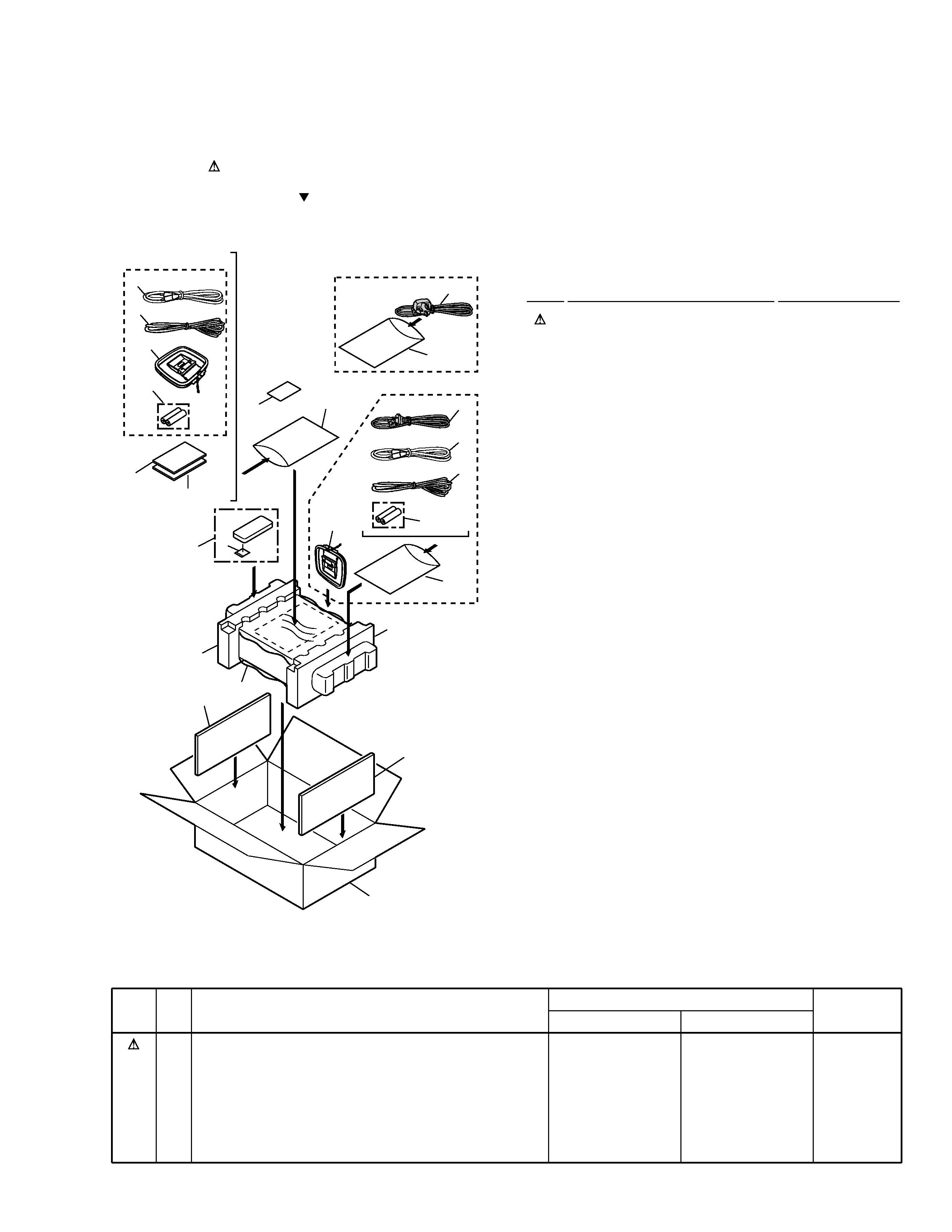
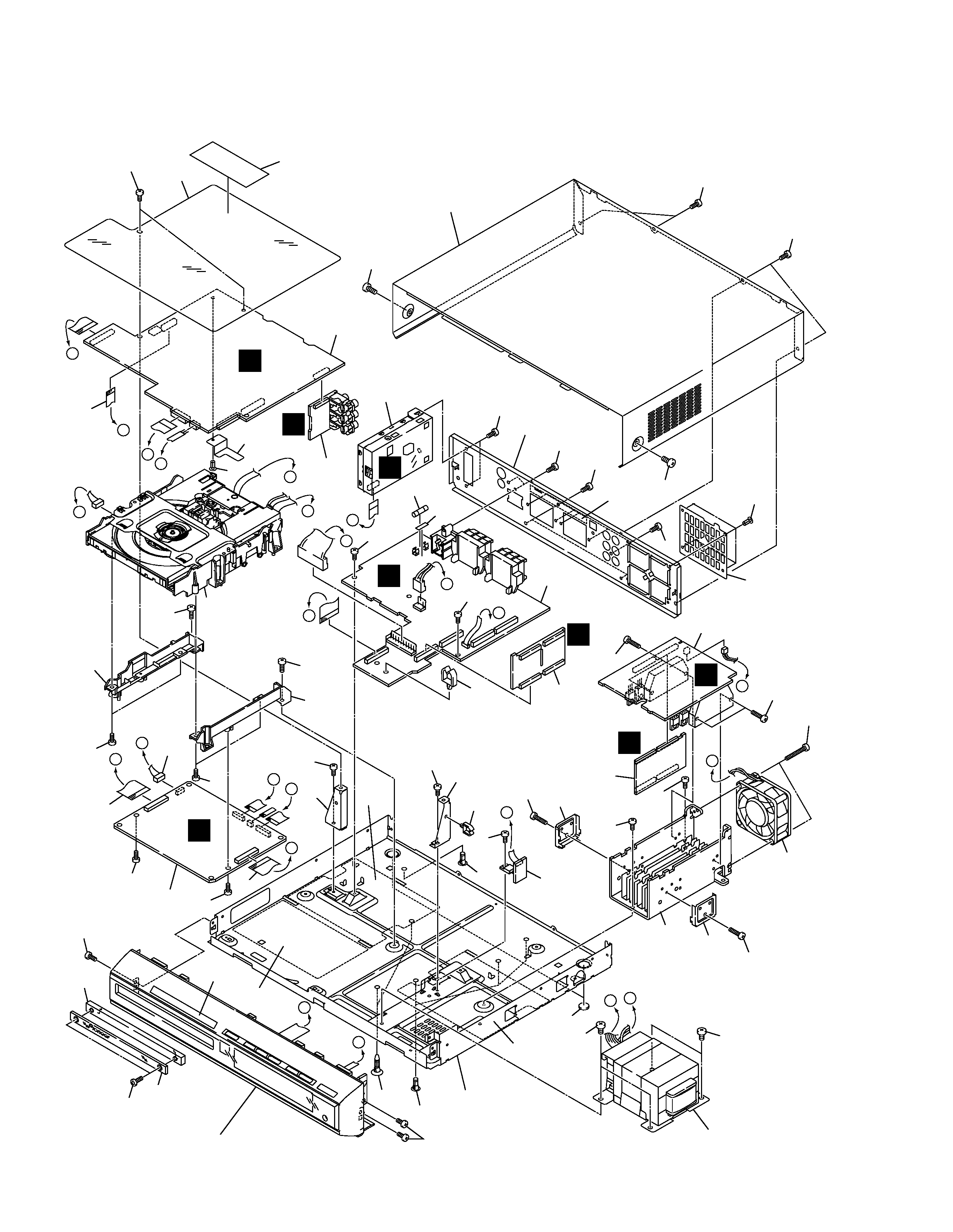
2. EXPLODED VIEWS AND PARTS LIST ................. 3
3. BLOCK DIAGRAM AND SCHEMATIC DIAGRAM ... 10
4. PCB CONNECTION DIAGRAM ........................... 45
5. PCB PARTS LIST ................................................ 58
6. ADJUSTMENT ..................................................... 64
CONTENTS
7. GENERAL INFORMATION ................................ 71
7.1 DIAGNOSIS .................................................. 71
7.1.1 SELF-DIAGNOSTIC FUNCTION OF
PICKUP DEFECTIVE ........................... 71
7.1.2 TEST POINTS LOCATION ................... 72
7.1.3 TEST MODE SCREEN DISPLAY ........ 73
7.1.4 TROUBLE SHOOTING ........................ 77
7.1.5 ERROR CODE ..................................... 78
7.1.6 DISASSEMBLY .................................... 82
7.2 PARTS .......................................................... 87
7.2.1 IC .......................................................... 87
7.2.2 DISPLAY ............................................... 89
8. PANEL FACILITIES AND SPECIFICATIONS .... 90