PIONEER XV-DV222/MYXJN Service Manual

Cover page of PIONEER XV-DV222/MYXJN Service Manual

Service Manual for PIONEER XV-DV222/MYXJN, downloadable as a PDF file.

We also have owner's manual to this model.

Manual details

  • Immediate download after payment.
  • Delivered as a PDF file.
  • The manual has 149 pages
  • File size: 9.59 MB
  • Available language versions: English
  • Different language versions may vary sligthly in file size and page count.

We guarantee that...

  • our manuals are complete,
  • the manual includes circuit diagrams,
  • our manuals are checked with antivirus,
  • We'll issue refund if the manual is damaged, incomplete or unreadable (our refund policy)

Sample pages

Thumbnail of page 1Thumbnail of page 2Thumbnail of page 3Thumbnail of page 4
Thumbnail of page 5Thumbnail of page 6Thumbnail of page 7Thumbnail of page 8
Thumbnail of page 9
background image
ORDER NO.
PIONEER CORPORATION 4-1, Meguro 1-chome, Meguro-ku, Tokyo 153-8654, Japan
PIONEER ELECTRONICS (USA) INC. P.O. Box 1760, Long Beach, CA 90801-1760, U.S.A.
PIONEER EUROPE NV Haven 1087, Keetberglaan 1, 9120 Melsele, Belgium
PIONEER ELECTRONICS ASIACENTRE PTE. LTD. 253 Alexandra Road, #04-01, Singapore 159936
PIONEER CORPORATION 2003
RRV2772
DVD/CD RECEIVER
XV-DV515
T ­ ZZV MAY. 2003 Printed in Japan
XV-DV515
0 OPEN/CLOSE
6
DVD/CD
FM/AM
­ DOWN
VOLUME
UP+
STANDBY/ON
PHONES
7
7
XV-DV313
Model
Types
Power Requirement
Region No.
Remarks
XV-DV515
MYXJ
AC220-230V
2
XV-DV515
NVXJ
AC230V
2
XV-DV313
MYXJN
AC220V-230V
2
XV-DV313
NVXJN
AC230V
2
THIS MANUAL IS APPLICABLE TO THE FOLLOWING MODEL(S) AND TYPE(S).
For details, refer to "Important symbols for good services" on the next page.
background image
2
1
23
4
12
3
4
C
D
F
A
B
E
XV-DV515
This service manual is intended for qualified service technicians ; it is not meant for the casual do-
it-yourselfer. Qualified technicians have the necessary test equipment and tools, and have been
trained to properly and safely repair complex products such as those covered by this
manual.Improperly performed repairs can adversely affect the safety and reliability of the product
and may void the warranty. If you are not qualified to perform the repair of this product properly and
safely, you should not risk trying to do so and refer the repair to a qualified service technician.
WARNING !
THE AEL (ACCESSIBLE EMISSION LEVEL) OF THE LASER POWER OUTPUT IS LESS THAN CLASS 1
BUT THE LASER COMPONENT IS CAPABLE OF EMITTING RADIATION EXCEEDING THE LIMIT FOR
CLASS 1.
A SPECIALLY INSTRUCTED PERSON SHOULD DO SERVICING OPERATION OF THE APPARATUS.
LASER DIODE CHARACTERISTICS
FOR DVD : MAXIMUM OUTPUT POWER : 5 mW
WAVELENGTH : 650 nm
FOR CD :
MAXIMUM OUTPUT POWER : 7 mW
WAVELENGTH : 780 nm
Additional Laser Caution
: See page 90.
1. Laser Interlock Mechanism
· Loading switch (S101 on the LOAB Assy) is used for interlock
mechanism of the laser.
When this switch turned ON in SW2 (CLOSE) side (OPEN signal is
0V and CLOSE signal is 3.5V), a laser becomes the status which can
completely oscillation.
Furthermore, the laser completely oscillates in the disc judgment and
disc playback.
When player is power ON state and laser diode is not completely
oscillating, 780nm laser diode is always oscillating by half power.
· Laser diode is driving with Q201 (650nm LD) and Q211 (780nm LD)
on the DVDM Assy.
Therefore, when short-circuit between the emitter and collector of these
transistors or the base voltage is supplied for transistors turn on, the
laser oscillates. (failure mode)
· In the test mode
, there is the mode that the laser oscillates except
for the disc judgment and playback. LD ON mode in the test mode
oscillates with the laser forcibly.
The interlock mechanism mentioned above becomes invalid in this
mode.
2. When the cover is open, close viewing through the objective lens with
the naked eye will cause exposure to the laser beam.
LABEL CHECK
VRW1872
Name Label
SAFETY INFORMATION
background image
3
1
23
4
1
2
3
4
C
D
F
A
B
E
XV-DV515
[ Important symbols for good services ]
In this manual, the symbols shown-below indicate that adjustments, settings or cleaning should be made securely.
When you find the procedures bearing any of the symbols, be sure to fulfill them:
2. Adjustments
To keep the original performances of the product, optimum adjustments or specification confirmation is indispensable.
In accordance with the procedures or instructions described in this manual, adjustments should be performed.
3. Cleaning
For optical pickups, tape-deck heads, lenses and mirrors used in projection monitors, and other parts requiring cleaning,
proper cleaning should be performed to restore their performances.
5. Lubricants, glues, and replacement parts
Appropriately applying grease or glue can maintain the product performances. But improper lubrication or applying
glue may lead to failures or troubles in the product. By following the instructions in this manual, be sure to apply the
prescribed grease or glue to proper portions by the appropriate amount.For replacement parts or tools, the prescribed
ones should be used.
4. Shipping mode and shipping screws
To protect the product from damages or failures that may be caused during transit, the shipping mode should be set or
the shipping screws should be installed before shipping out in accordance with this manual, if necessary.
1. Product safety
You should conform to the regulations governing the product (safety, radio and noise, and other regulations), and
should keep the safety during servicing by following the safety instructions described in this manual.
background image
4
1
23
4
12
3
4
C
D
F
A
B
E
XV-DV515
CONTENTS
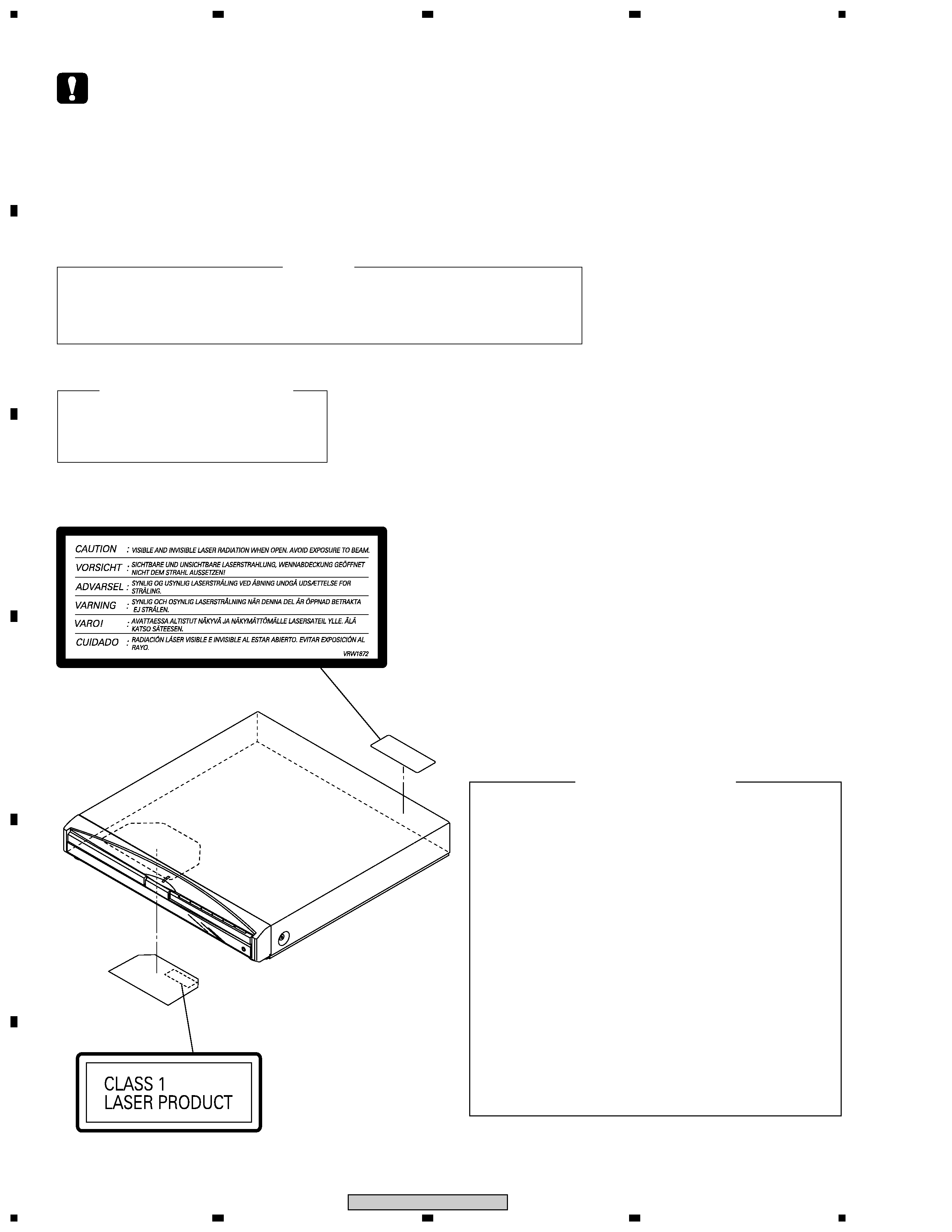
SAFETY INFORMATION ...................................................................................................................................... 2
1. SPECIFICATIONS ............................................................................................................................................ 5
2. EXPLODED VIEWS AND PARTS LIST .......................................................................................................... 8
2.1 PACKING .................................................................................................................................................... 8
2.2 EXTERIOR SECTION ............................................................................................................................. 10
2.3 FRONT SECTION ................................................................................................................................... 12
2.4 LOADING MECANISM ASSY ................................................................................................................. 14
2.5 TRAVERSE MECHANISM ASSY ........................................................................................................... 17
3. BLOCK DIAGRAM AND SCHEMATIC DIAGRAM ........................................................................................ 18
3.1 BLOCK DIAGRAM ................................................................................................................................... 18
3.2 LOAB ASSY and OVERALL WIRING DIAGRAM ................................................................................... 20
3.3 DVDM ASSY (1/3) ................................................................................................................................... 22
3.4 DVDM ASSY (2/3) ................................................................................................................................... 24
3.5 DVDM ASSY (3/3) ................................................................................................................................... 26
3.6 DSP ASSY (1/2) ...................................................................................................................................... 28
3.7 DSP ASSY (2/2) ...................................................................................................................................... 30
3.8 6CH AMP ASSY ...................................................................................................................................... 32
3.9 FM/AM TUNER MODULE ....................................................................................................................... 34
3.10 CONTROL (1/4), TRADE3 and TRADE2 ASSYS ................................................................................ 36
3.11 CONTROL ASSY (2/4) .......................................................................................................................... 38
3.12 CONTROL ASSY (3/4) .......................................................................................................................... 40
3.13 CONTROL (4/4) and HP ASSYS .......................................................................................................... 42
3.14 POWER ASSY (1/2 ) ............................................................................................................................. 44
3.15 POWER (2/2) and TRADE1 ASSYS ..................................................................................................... 46
3.16 EURO SCART ASSY ............................................................................................................................ 48
3.17 DISPLAY and LED ASSYS ................................................................................................................... 50
3.18 WAVEFORMS ....................................................................................................................................... 52
4. PCB CONNECTION DIAGRAM ..................................................................................................................... 54
4.1 LOAB ASSY ............................................................................................................................................ 54
4.2 DVDM ASSY ........................................................................................................................................... 55
4.3 DSP ASSY ............................................................................................................................................... 57
4.4 6CH AMP ASSY ...................................................................................................................................... 59
4.5 FM/AM TUNER MODULE ....................................................................................................................... 61
4.6 CONTROL ASSY .................................................................................................................................... 62
4.7 TRADE2 ,TRADE3 and HP ASSYS ........................................................................................................ 66
4.8 POWER ASSY ........................................................................................................................................ 68
4.9 TRADE1, EURO SCART, DISPLAY and LED ASSYS ........................................................................... 72
5. PCB PARTS LIST .......................................................................................................................................... 76
6. ADJUSTMENT ............................................................................................................................................... 83
7. GENERAL INFORMATION ............................................................................................................................ 90
7.1 DIAGNOSIS ............................................................................................................................................. 90
7.1.1 TEST MODE .................................................................................................................................... 90
7.1.2 DISPLAY SPECIFICATIONS OF THE TEST MODE ...................................................................... 92
7.1.3 FUNCTIONAL SPECIFICATION OF THE SHORTCUT KEY ......................................................... 93
7.1.4 SPECIFICATION OF MODEL INFORMATION DISPALY ............................................................. 94
7.1.5 FUNCTIONAL SPECIFICATION OF THE SERVICE MODE .......................................................... 95
7.1.6 MECHANICAL ERROR HISTORY ..................................................................................................96
7.1.7 ID NUMBER AND DATA SETTING ............................................................................................... 101
7.1.8 TROUBLE SHOOTING .................................................................................................................. 104
7.1.9 DSP TROUBLE SHOOTING ......................................................................................................... 107
7.1.10 SEQUENCE AFTER POWER ON ............................................................................................... 111
7.1.11 PROTECTION CIRCUIT .............................................................................................................. 112
7.1.12 DISASSEMBLY ............................................................................................................................ 117
7.2 IC ........................................................................................................................................................... 126
7.3 DISC / CONTENT FORMAT PLAYBACK COMPATIBILITY ................................................................ 142
7.4 CLEANING ............................................................................................................................................ 143
8. PANEL FACILITIES ..................................................................................................................................... 144
background image
5
1
23
4
1
2
3
4
C
D
F
A
B
E
XV-DV515
Amplifier section
Continuous Power Output (RMS):
Front, center, surround. . . . . 75 W per channel
(1 kHz, 10 % T.H.D., 6
)
Subwoofer . . . 75 W (100 Hz, 10 % T.H.D., 6
)
Continuous Power Output :
Front, center, surround. . . . . 62 W per channel
(1 kHz, 1 % T.H.D., 6
)
Subwoofer . . . . 62 W (100 Hz, 1 % T.H.D., 6
)
Disc section
Digital audio
characteristics . . . . . . . DVD fs: 96 kHz, 24-bit
Type. . . . . . DVD system, video CD system and
compact disc digital audio system
Frequency response . . . . . . . . . 4 Hz to 44 kHz
Wow and Flutter. . . . . . .Limit of measurement
(
±0.001 % W.PEAK) or less (JEITA)
FM tuner section
Frequency range . . . . . . . . . . . 87.5 ­ 108 MHz
Antenna . . . . . . . . . . . . . . . .75
, unbalanced
AM tuner section
Frequency range
With 9kHz step. . . . . . . 531 kHz to 1,602 kHz
Antenna . . . . . . . . . . . . . . . . . . . Loop antenna
Miscellaneous
Power requirements
European model . . . AC 220-230 V, 50/60 Hz
U.K. model . . . . . . . . . . . AC 230 V, 50/60 Hz
Power consumption
European/U.K. model . . . . . . . . . . . . . 160 W
Power consumption in standby . . . . . . 0.39 W
Dimensions . . .420 (W) x 70 (H) x 403.5 (D) mm
Weight . . . . . . . . . . . . . . . . . . . . . . . . . . 7.4 kg
Accessories (DVD/CD receiver)
Remote control . . . . . . . . . . . . . . . . . . . . . . . . .
1
AA/R6 dry cell batteries. . . . . . . . . . . . . . . . . 2
Video cable (yellow plugs). . . . . . . . . . . . . . . .1
AM loop antenna . . . . . . . . . . . . . . . . . . . . . . 1
FM antenna . . . . . . . . . . . . . . . . . . . . . . . . . .1
Power cord . . . . . . . . . . . . . . . . . . . . . . . . . . .1
Setup Guide. . . . . . . . . . . . . . . . . . . . . . . . . . .1
These operating instructions. . . . . . . . . . . . . .1
Warranty Card . . . . . . . . . . . . . . . . . . . . . . . .1
Speaker System
Front speakers
Enclosure . . . . . . . . Closed-box bookshelf type
(magnetically shielded)
System. . . . . . . . . . . . . .15x6 cm 1-way system
Speakers . . . . . . . . . . . . . . .15x6 cm cone type
Nominal impedance . . . . . . . . . . . . . . . . . . 6
Frequency range . . . . . . . . . . .90 Hz to 20 kHz
Maximum Input Power. . . . . . . . . . . . . . . 75 W
Dimensions . . . . . 78 (W) x 210 (H) x 82 (D) mm
Weight . . . . . . . . . . . . . . . . . . . . . . . . . . 0.7 kg
Center speaker
Enclosure . . . . . . . . Closed-box bookshelf type
(magnetically shielded)
System. . . . . . . . . . . . . .15x6 cm 1-way system
Speakers . . . . . . . . . . . . . . .15x6 cm cone type
Nominal impedance . . . . . . . . . . . . . . . . . . 6
Frequency range . . . . . . . . . . .78 Hz to 20 kHz
Maximum Input Power. . . . . . . . . . . . . . . 75 W
Dimensions . . . . . 240 (W) x 85 (H) x 96 (D) mm
Weight . . . . . . . . . . . . . . . . . . . . . . . . . 0.75 kg
1. SPECIFICATIONS

Reviews

There are no reviews of this manual yet.