XV-DV1000
5
5
678
56
7
8
C
D
F
A
B
E
CONTENTS
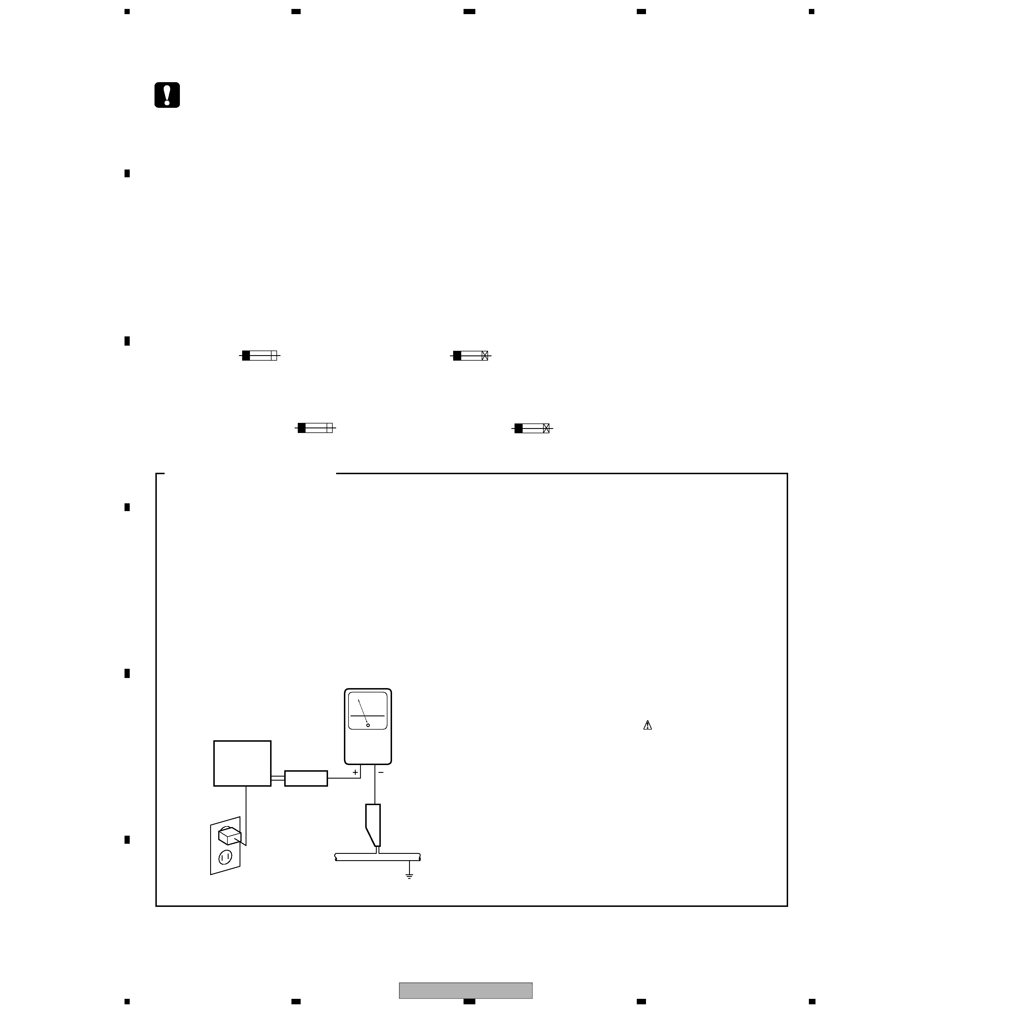
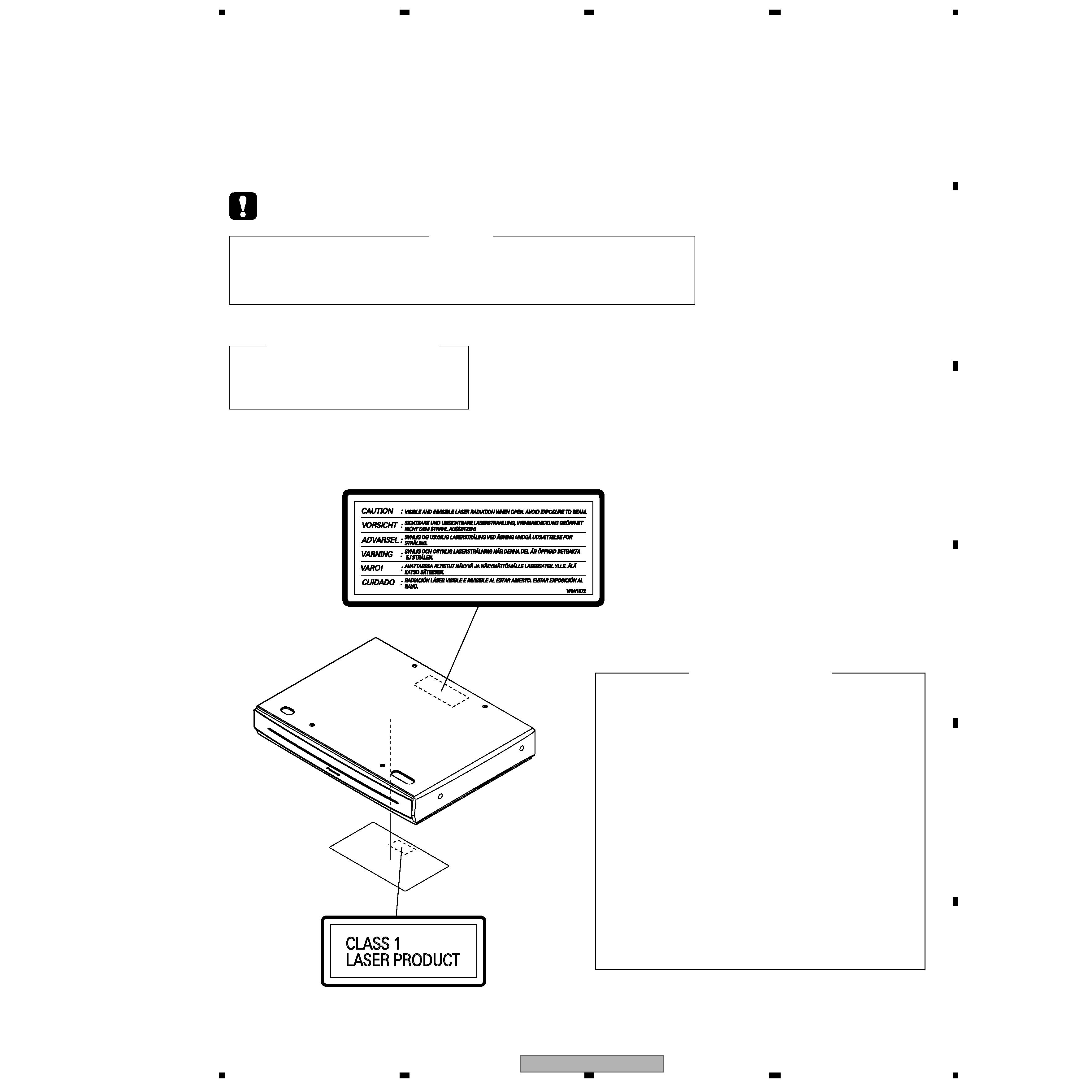
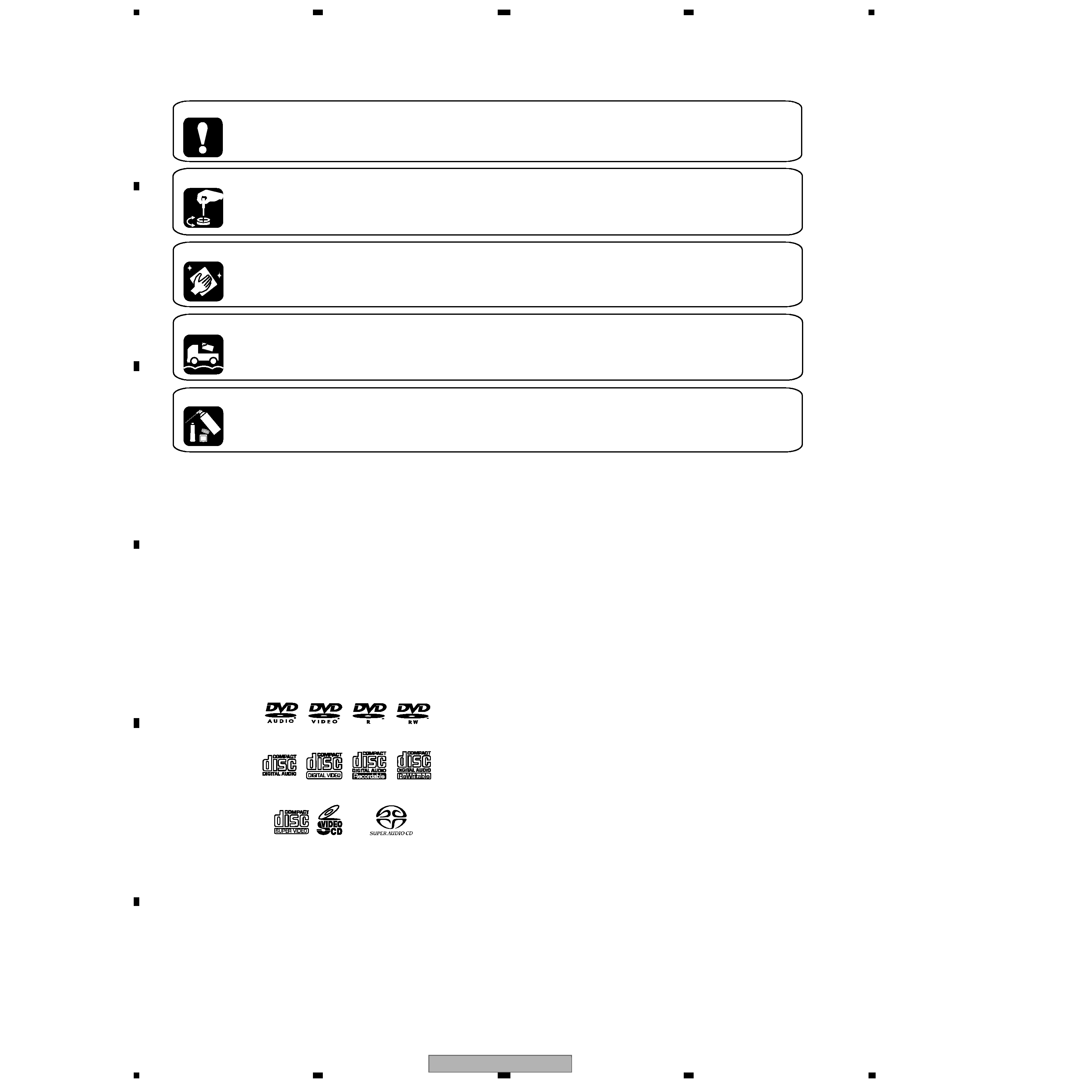
SAFETY INFORMATION.......................................................................................................................................................2
1. SPECIFICATIONS ..............................................................................................................................................................6
2. EXPLODED VIEWS AND PARTS LIST..............................................................................................................................8
2.1 PACKING .....................................................................................................................................................................8
2.2 EXTERIOR SECTION ...............................................................................................................................................10
2.3 FRONT PANEL SECTION .........................................................................................................................................12
2.4 LOADING MECHA ASSY ..........................................................................................................................................14
2.5 TRAVERSE MECHANISM ASSY-S ...........................................................................................................................16
2.6 DISPLAY UNIT ..........................................................................................................................................................17
3. BLOCK DIAGRAM AND SCHEMATIC DIAGRAM ...........................................................................................................18
3.1 DVD and Video Section BLOCK DIAGRAM ..............................................................................................................18
3.2 DSP and Control Section BLOCK DIAGRAM ............................................................................................................20
3.3 Power Supply Section BLOCK DIAGRAM .................................................................................................................22
3.4 LOAB ASSY and OVERALL WIRING DIAGRAM ......................................................................................................24
3.5 DVDM ASSY (1/4) .....................................................................................................................................................26
3.6 DVDM ASSY (2/4) .....................................................................................................................................................28
3.7 DVDM ASSY (3/4) .....................................................................................................................................................30
3.8 DVDM ASSY (4/4) .....................................................................................................................................................32
3.9 SACDB ASSY ............................................................................................................................................................34
3.10 VIDEO (1/2) and REG ASSYS.................................................................................................................................36
3.11 VIDEO (2/2) and COMPONENT ASSYS .................................................................................................................38
3.12 IF ASSY ...................................................................................................................................................................40
3.13 FM/AM TUNER MODULE (AXQ7228).....................................................................................................................42
3.14 FM/AM TUNER MODULE (AXQ7229).....................................................................................................................44
3.15 DSP ASSY...............................................................................................................................................................46
3.16 DSP TRADE and CONTROL (1/4) ASSYS .............................................................................................................48
3.17 CONTROL ASSY (2/4) ............................................................................................................................................50
3.18 CONTROL ASSY (3/4) ............................................................................................................................................52
3.19 CONT.(4/4), STBY KEY, D.SW2, KEY L, TIMER LED, KEY R, O/C KEY, MOTOR, D.SW, and HP ASSYS..............54
3.20 OEL CONT and OEL JACK ASSYS ........................................................................................................................56
3.21 WAVEFORMS..........................................................................................................................................................58
4. PCB CONNECTION DIAGRAM .......................................................................................................................................59
4.1 LOAB ASSY...............................................................................................................................................................59
4.2 DVDM ASSY..............................................................................................................................................................60
4.3 SACDB ASSY ............................................................................................................................................................62
4.4 FM/AM TUNER MODULE..........................................................................................................................................63
4.5 VIDEO, REG and COMPONENT ASSYS..................................................................................................................64
4.6 IF ASSY .....................................................................................................................................................................68
4.7 DSP ASSY.................................................................................................................................................................70
4.8 DSP TRADE ASSY....................................................................................................................................................71
4.9 CONTROL, MOTOR, DOOR SW and HP ASSYS.....................................................................................................72
4.10 STBY KEY, DOOR SW2, KEY L, TIMER LED, KEY R and O/C KEY ASSYS.........................................................76
4.11 OEL CONT and OEL JACK ASSYS ........................................................................................................................78
5. PCB PARTS LIST .............................................................................................................................................................79
6. ADJUSTMENT .................................................................................................................................................................89
6.1 DVD SECTION ADJUSTMENT .................................................................................................................................89
6.1.1 Adjustment Items and Location ..............................................................................................................................89
6.1.2 Jigs and Measuring Instruments.............................................................................................................................89
6.1.3 Necessary Adjustment Points.................................................................................................................................90
6.1.4 Test Mode ...............................................................................................................................................................91
6.1.5 Mechanism Adjustment ..........................................................................................................................................92
6.2 TUNER SECTION ADJUSTMENT ............................................................................................................................95
7. GENERAL INFORMATION ..............................................................................................................................................96
7.1 DIAGNOSIS ...............................................................................................................................................................96
7.1.1 ID NUMBER AND ID DATA SETTING ....................................................................................................................96
7.1.2 SELF-DIAGNOSIS FUNCTION OF PICKUP DETECTIVE ....................................................................................98
7.1.3 TEST MODE SCREEN DISPLAY ...........................................................................................................................99
7.1.4 SELF-DIAGNOSIS FUNCTION ............................................................................................................................101
7.1.5 FUNCTION SPECIFICATION OF THE SERVICE MODE.....................................................................................102
7.1.6 ERROR DISPLAY .................................................................................................................................................103
7.1.7 TEST POINTS LOCATION AND WAVEFORMS...................................................................................................106
7.1.8 TROUBLE SHOOTING .........................................................................................................................................108
7.1.9 SERVICE TEST MODE ........................................................................................................................................109
7.1.10 STANDBY ON TIMING WAVEFORM..................................................................................................................110
7.1.11 SINGLE OPERATION METHOD ........................................................................................................................111
7.1.12 DISASSEMBLY...................................................................................................................................................112
7.2 IC .............................................................................................................................................................................121
7.3 CLEANING ..............................................................................................................................................................160
8. PANEL FACILITIES ........................................................................................................................................................161