XV-CX505
4
12
34
1
234
C
D
F
A
B
E
CONTENTS
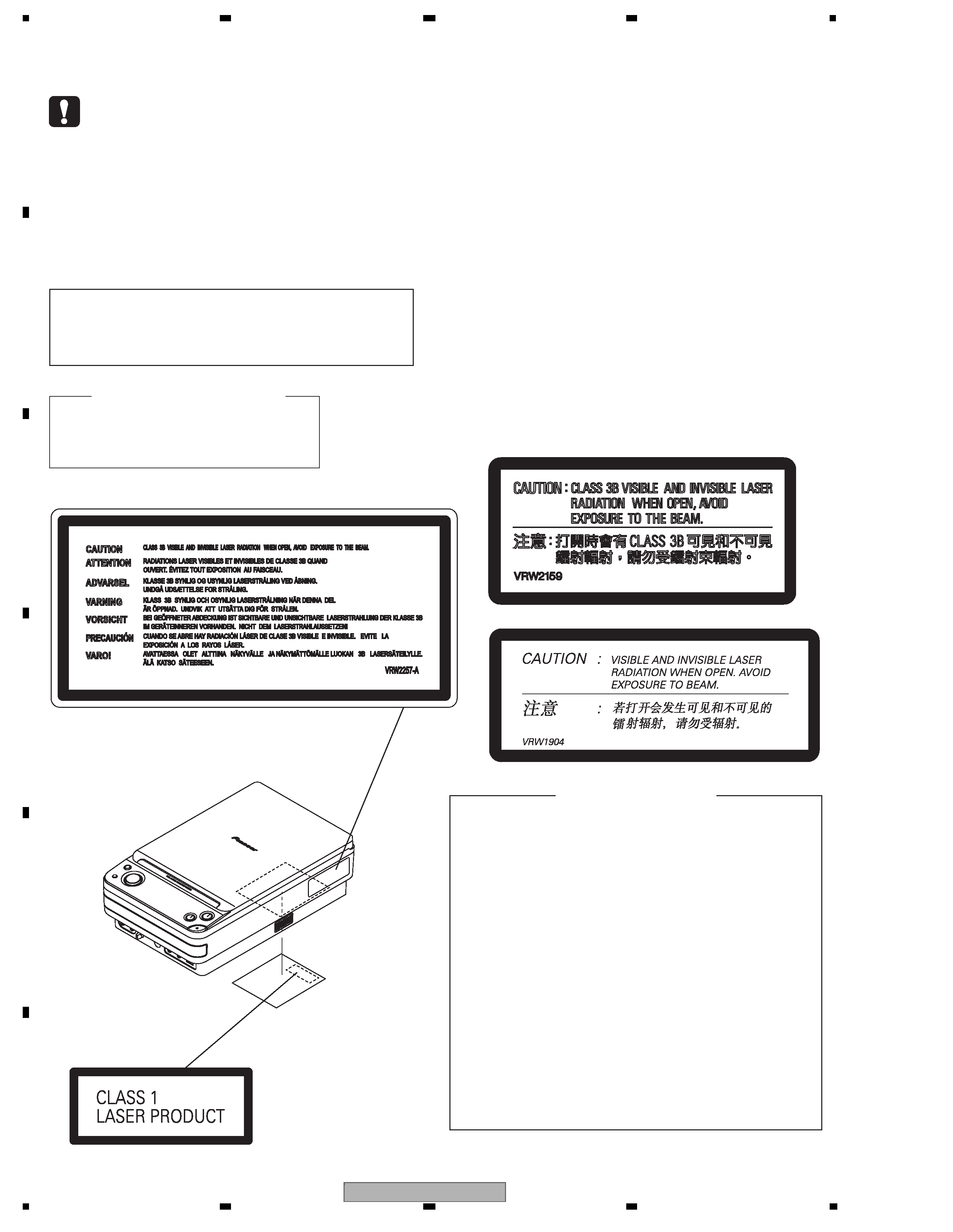
SAFETY INFORMATION ..................................................................................................................................... 2
1. SERVICE PRECAUTIONS ............................................................................................................................... 5
2. SPECIFICATIONS ............................................................................................................................................ 6
2.1 SPECIFICATIONS and ACCESORRIES ................................................................................................... 6
2.2 PANEL FACILITIES .................................................................................................................................... 8
3. BASIC ITEMS FOR SERVICE........................................................................................................................ 10
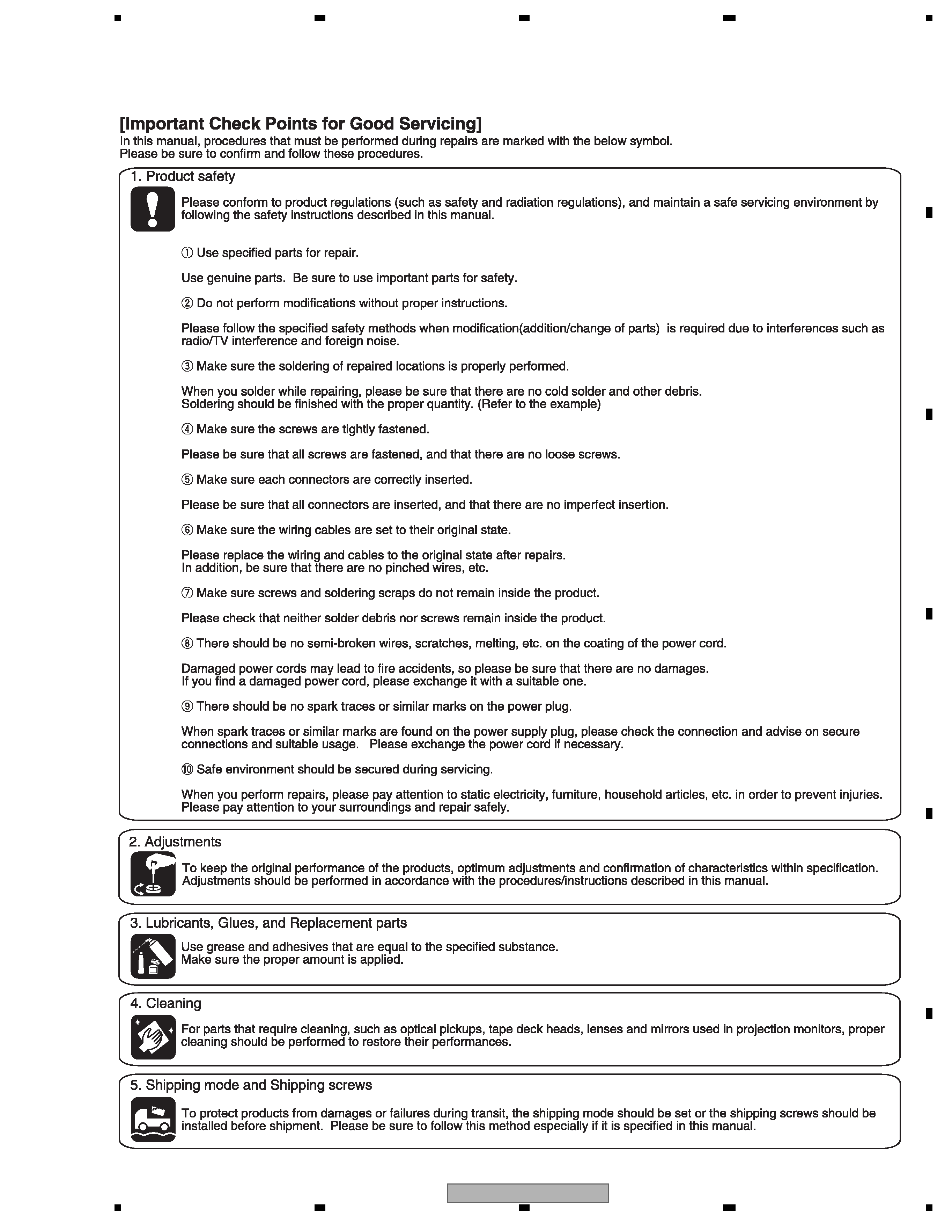
3.1 CHECK POINTS AFTER SERVICING..................................................................................................... 10
3.2 PCB LOCATIONS .................................................................................................................................... 11
3.3 JIGS LIST ................................................................................................................................................ 12
3.4 CLEANING............................................................................................................................................... 12
4. BLOCK DIAGRAM.......................................................................................................................................... 14
4.1 OVERALL WIRING CONNECTION DIAGRAM and LOAB ASSY ........................................................... 14
4.2 OVERALL BLOCK DIAGRAM.................................................................................................................. 16
5. DIAGNOSIS.................................................................................................................................................... 18
5.1 METHOD FOR DIAGNOSING DEGRADATION OF THE LDS ON THE PICKUP ................................... 18
5.2 DVD TROUBLE SHOOTING.................................................................................................................... 19
5.3 CIRCUIT DESCRIPTION OF DIGITAL AMP. SECTION .......................................................................... 22
5.4 SPECIFICATIONS FOR THE PROTECTION CIRCUITS FOR THE DIGITAL AMPLIFIER ..................... 23
6. SERVICE MODE ............................................................................................................................................ 24
6.1 TEST MODE ............................................................................................................................................ 24
6.2 DISPLAY SPECIFICATION OF THE TEST MODE .................................................................................. 25
6.3 FUNCTIONAL SPECIFICATION OF THE SHORTCUT KEY................................................................... 26
6.4 SPECIFICATION OF MODEL INFORMATION DISPLAY......................................................................... 27
6.5 FUNCTIONAL SPECIFICATION OF THE SERVICE MODE ................................................................... 28
6.6 SERVICE TEST MODE ........................................................................................................................... 29
7. DISASSEMBLY............................................................................................................................................... 32
8. EACH SETTING AND ADJUSTMENT ........................................................................................................... 43
8.1 ADJUSTMENT ......................................................................................................................................... 43
8.2 ID NUMBER AND ID DATA SETTING...................................................................................................... 48
9. EXPLODED VIEWS AND PARTS LIST.......................................................................................................... 52
9.1 PACKING SECTION ................................................................................................................................ 52
9.2 MAIN UNIT SECTION.............................................................................................................................. 54
9.3 POWER UNIT SECTION ......................................................................................................................... 56
9.4 06 LOADER ASSY................................................................................................................................... 58
9.5 TRAVERSE MECHANISM ASSY-S ......................................................................................................... 60
10. SCHEMATIC DIAGRAM ............................................................................................................................... 62
10.1 DVD MAIN ASSY (1/5)........................................................................................................................... 62
10.2 DVD MAIN ASSY (2/5)........................................................................................................................... 64
10.3 DVD MAIN ASSY (3/5)........................................................................................................................... 66
10.4 DVD MAIN ASSY (4/5)........................................................................................................................... 68
10.5 DVD MAIN ASSY (5/5)........................................................................................................................... 70
10.6 HAMP ASSY (1/2).................................................................................................................................. 72
10.7 HAMP ASSY (2/2).................................................................................................................................. 74
10.8 DISPLAY ASSY...................................................................................................................................... 76
10.9 HP/MIC, REGULATOR TRADE and DVD TRADE ASSYS .................................................................... 78
10.10 POWER SUPPLY UNIT........................................................................................................................ 80
10.11 WAVEFORMS ...................................................................................................................................... 82
11. PCB CONNECTION DIAGRAM ................................................................................................................... 84
11.1 LOAB ASSY ........................................................................................................................................... 84
11.2 POWER SUPPLY UNIT.......................................................................................................................... 85
11.3 DVD MAIN ASSY ................................................................................................................................... 86
11.4 HAMP ASSY .......................................................................................................................................... 90
11.5 DISPLAY, HP/MIC, DVD TRADE and REGULATOR TRADE ASSYS.................................................... 92
12. PCB PARTS LIST ......................................................................................................................................... 96