2
XR-A6800, XR-A4800
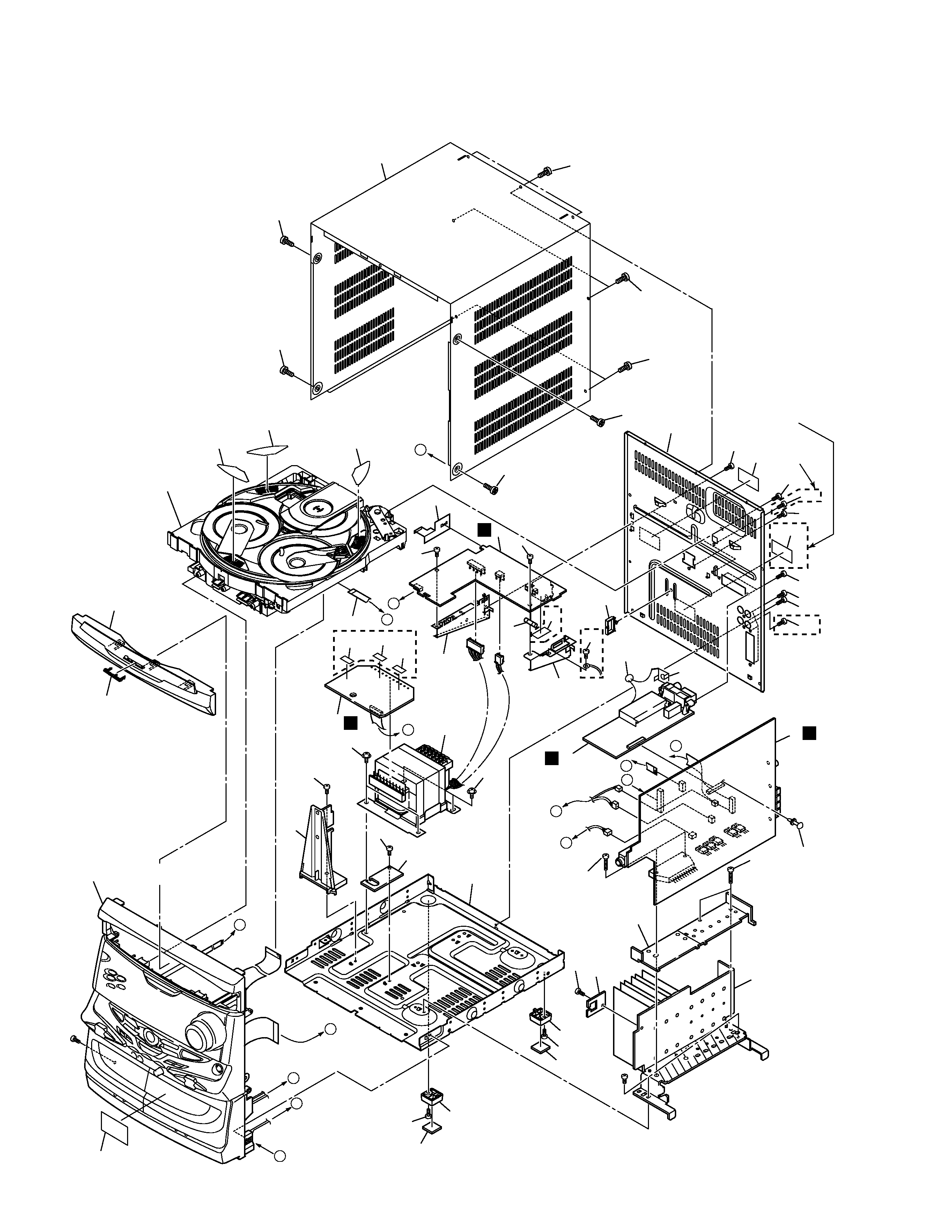
MYXJ Type
MYXJ Type
NVXJ Type
Printed on the Rear Panel
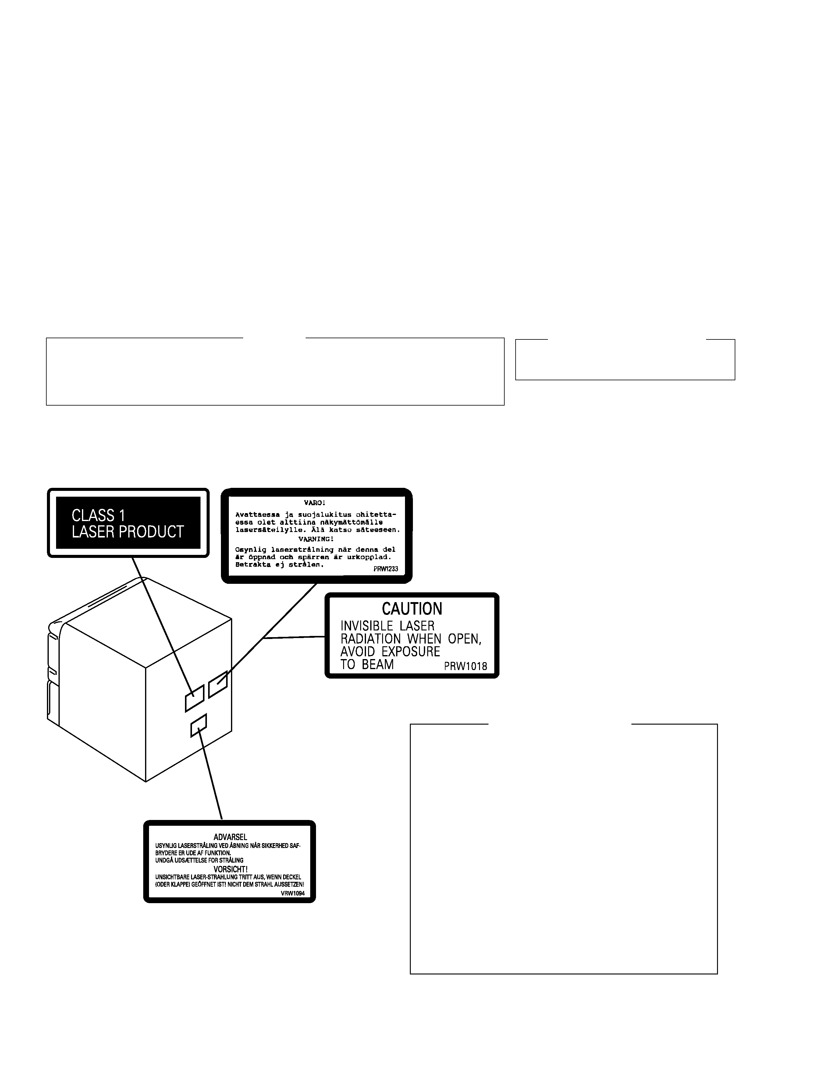
Additional Laser Caution
1. Laser Interlock Mechanism
The position of the switch (S9501) for detecting loading
state is detected by the system microprocessor, and
the design prevents laser diode oscillation when the
switch (S9501) is pressed physically.
Thus, the interlock will no longer function if the switch (S9501)
is released physically and deliberatery.
The interlock also does not function in the test mode
.
Laser diode oscillation will continue, if pin 1 of
CXA1821M (IC8101) on the CD ASSY mounted on the
$M Loading Mechanism assembly is connected to GND,
or else the terminals of Q8101 are shorted to each other
(fault condition).
2. When the cover is opened, close viewing of the objective
lens with the naked eye will cause exposure to a Class
1 laser beam.
: Refer to page 61.
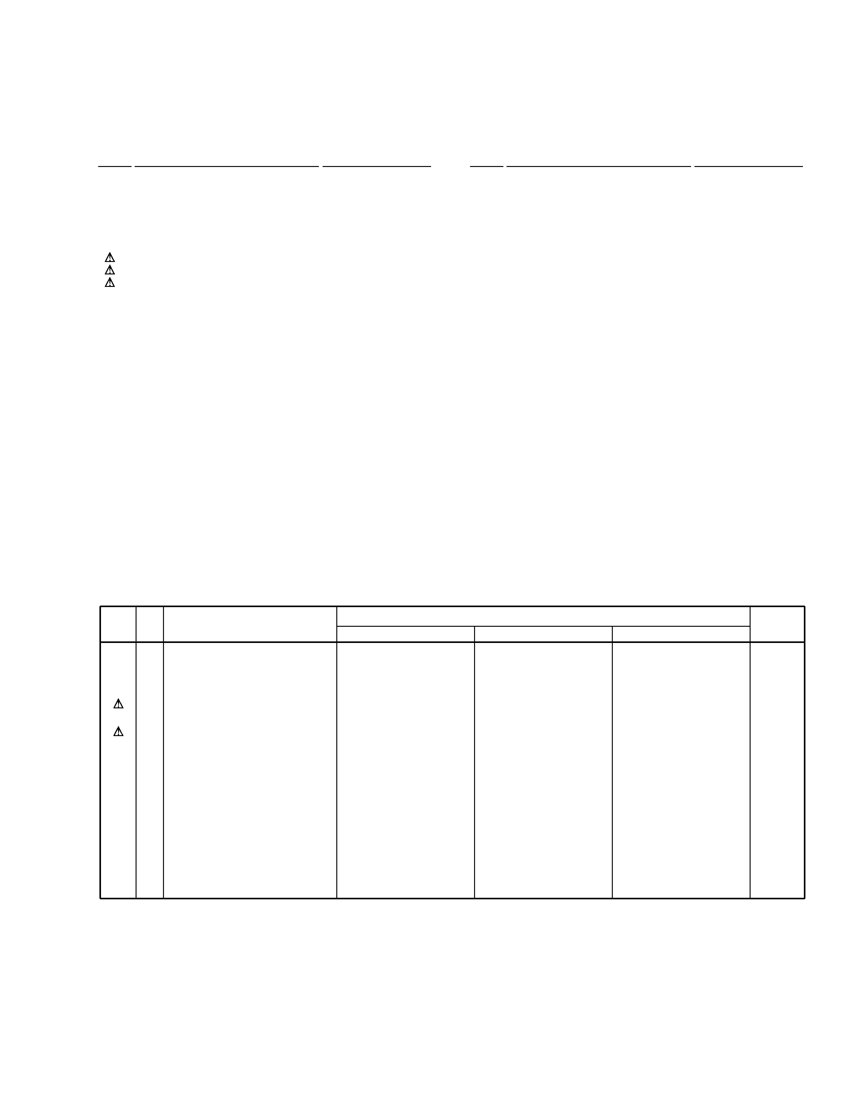
LABEL CHECK (For MYXJ and NVXJ Types)
LASER DIODE CHARACTERISTICS
MAXIMUM OUTPUT POWER: 5 mW
WAVELENGTH: 780 nm to 785 nm
WARNING !
THE AEL (ACCESSIBLE EMISSION LEVEL) OF THE LASER POWER OUTPUT IS LESS THAN CLASS 1
BUT THE LASER COMPONENT IS CAPABLE OF EMITTING RADIATION EXCEEDING THE LIMIT FOR
CLASS 1.
A SPECIALLY INSTRUCTED PERSON SHOULD DO SERVICING OPERATION OF THE APPARATUS.
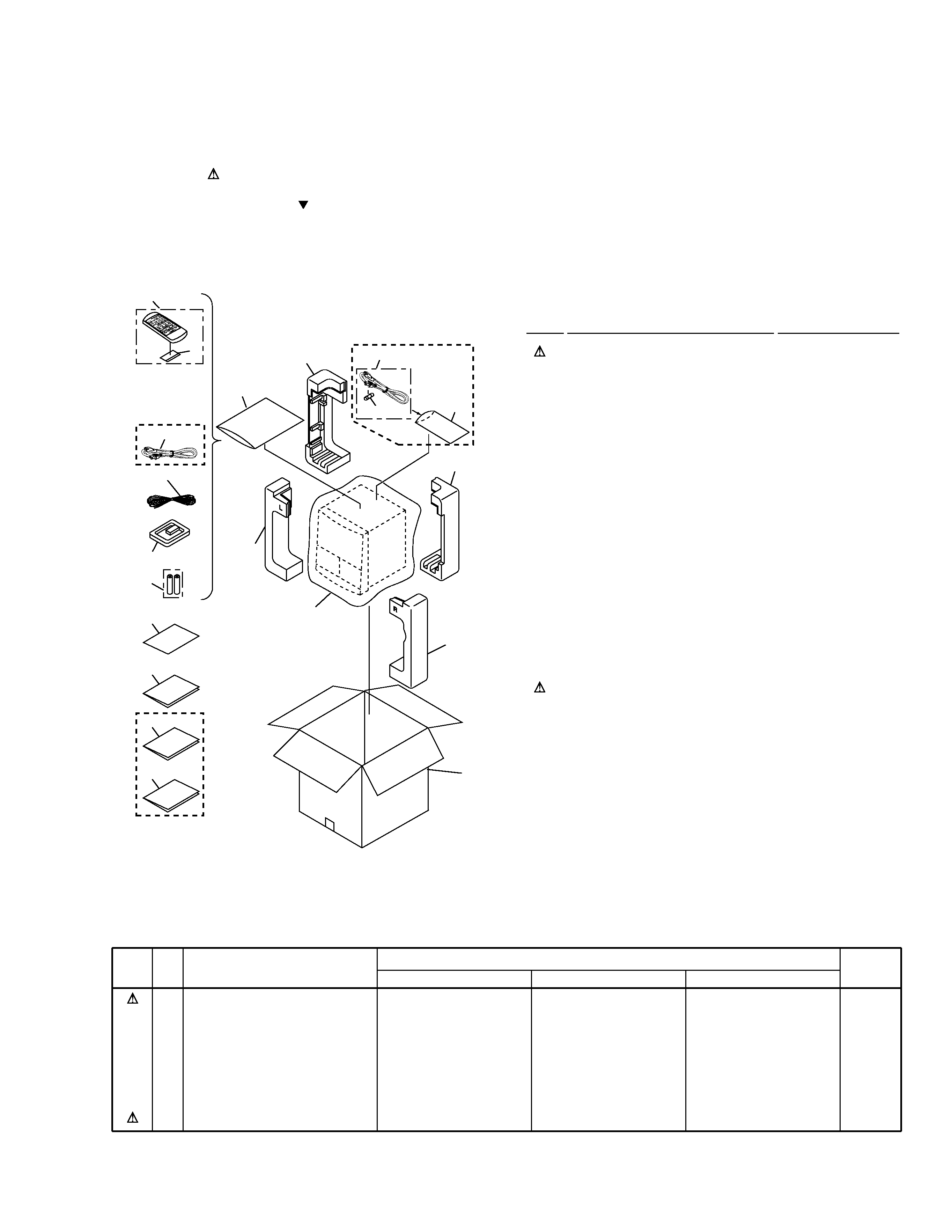
1. SAFETY INFORMATION
This service manual is intended for qualified service technicians ; it is not meant for the casual do-it-
yourselfer. Qualified technicians have the necessary test equipment and tools, and have been trained
to properly and safely repair complex products such as those covered by this manual.
Improperly performed repairs can adversely affect the safety and reliability of the product and may
void the warranty. If you are not qualified to perform the repair of this product properly and safely, you
should not risk trying to do so and refer the repair to a qualified service technician.


/KC Owner's Manual")


