XR-A670, XR-A370
3
2. CONTRAST OF MISCELLANEOUS PARTS
Parts marked by "NSP" are generally unavailable because they are not in our Master Spare Parts List.
The
mark found on some component parts indicates the importance of the safety factor of the part.
Therefore, when replacing, be sure to use parts of identical designation.
Screws adjacent to
mark on product are used for disassembly.
Reference Nos. indicate the pages and Nos. in the service manual for the base model.
NOTES:
When ordering resistors, first convert resistance values into code form as shown in the following examples.
Ex.1 When there are 2 effective digits (any digit apart from 0), such as 560 ohm and 47k ohm (tolerance is shown by J=5%,
and K=10%).
Ex.2 When there are 3 effective digits (such as in high precision metal film resistors).
561
473
R50
1R0
5621
560
47k
0.5
1
RD1/4PU
J
RD1/4PU
J
RN2H
K
RS1P
K
56 x 101
47 x 103
R50
1R0
561
473
5.62k
RN1/4PC
F
562 x 101
5621
CONTRAST TABLE for XR-A670
Part No.
Ref. No. Mark
Symbol and Description
XR-A670
XR-A670
XR-A670
XR-A670
Remarks
/KUCXJ
/DBDXJ
/DXJN/NC
/YPWXJ
PCB ASSEMBLIES
COMPLEX ASSY
XWM3113
XWM3111
XWM3111
XWM3112
P6- 2
PRIMARY ASSY
XWZ3224
XWZ3222
XWZ3222
XWZ3223
P6- 3
SUB TRANS ASSY
XWZ3227
XWZ3226
XWZ3226
XWZ3226
P9- 1
DISPLAY ASSY
XWZ3214
XWZ3212
XWZ3212
XWZ3212
PACKING SECTION
P4- 1
Power Cord
ADG7022
ADG1158
ADG1154
ADG1160
P4- 6
NSP
Dry Cell Battery (R6P, AA)
VEM-013
Not used
VEM-013
Not used
P4-10
Packing Case
XHD3091
XHD3093
XHD3095
XHD3092
P4-11
NSP
Warranty Card
ARY7033
Not used
Not used
ARY7027
P4-13
Operating Instructions (English/French)
XRE3024
Not used
Not used
XRE3024
P4-18
NSP
Polyethylene Bag
Not used
Not used
Not used
AHG7033
For Power Cord
Operating Instructions
Not used
XRE3025
Not used
Not used
(English/Chinese/Spanish)
Operating Instructions (Thai)
Not used
Not used
XRC3017
Not used
Power-cord Plug Conversion Adapter
Not used
XKM3002
Not used
Not used
Accessories
EXTERIOR SECTION
P6- 7
Power Transformer (AC120V)
XTS3032
Not used
Not used
Not used
P6- 7
Power Transformer
Not used
XTS3031
XTS3031
XTS3031
(AC110-127V/220-230V/240V)
P6- 8
Fuse (FU1 : 6.3A)
REK1085
Not used
Not used
Not used
P6- 8
Fuse (FU1 : T5A)
Not used
AEK1061
AEK1061
AEK1061
P6- 9
NSP
Fuse Caution Label
XAX3157
Not used
Not used
Not used
P6-20
Rear Panel
XNC3040
XNC3042
XNC3042
XNC3041
P6-35
NSP
Fuse Card
AAX2374
AAX7098
AAX7098
AAX7098
P6-39
Cushion Leg B
XEB3009
XEB3009
Not used
XEB3009
P6-43
NSP
Getter
XAX3143
XAX3145
XAX3145
XAX3144
P6-44
Caution Label
Not used
Not used
Not used
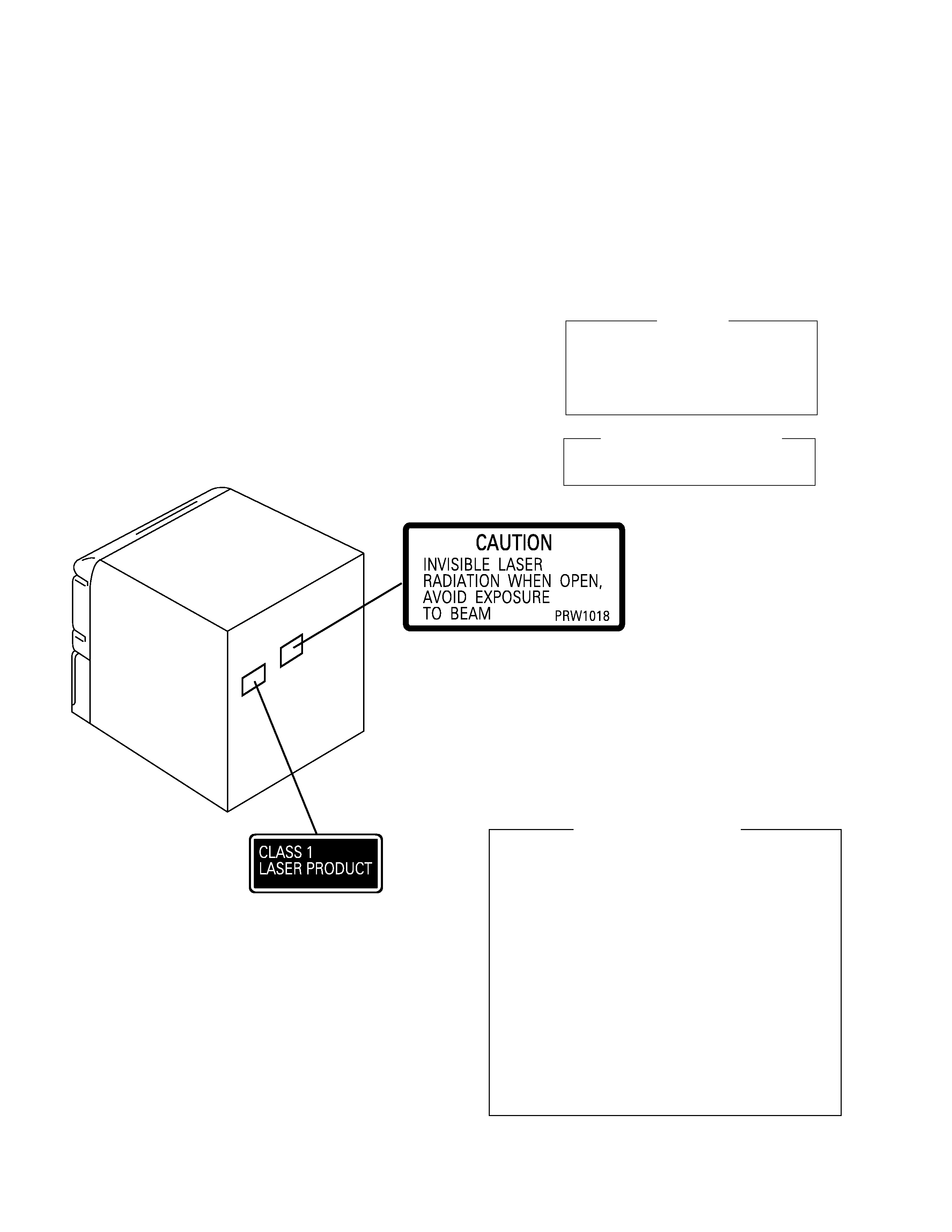
PRW1018
P6-45
65 Label
ORW1069
Not used
Not used
Not used
Fuse (FU2, FU3 : T3.15A)
Not used
AEK1059
AEK1059
Not used
*1
Fuse Card (For FU2, FU3)
Not used
AAX7493
AAX7493
Not used
*2
NSP
Name Label
Not used
Not used
XAL3035
Not used
*3
FRONT PANEL SECTION
P9-17
Display Panel
XAK3113
XAK3114
XAK3114
XAK3114
P9-19
FL Cover
XAK3088
XAK3124
XAK3124
XAK3124
XR-A670/DBDXJ, DXJN/NC, YPWXJ and XR-A670/KUCXJ are constructed the same except for the following :
Notes : For PCB ASSEMBLIES, Refer to "CONTRAST OF PCB ASSEMBLIES" and "3. SCHEMATIC DIAGRAM".
*1 Refer to "3. SCHEMATIC DIAGRAM".
*2 Stick Fuse Card on PRIMARY ASSY.
*3 Stick Name Label on Rear Panel.