2
X-MDX717, XR-MDX717
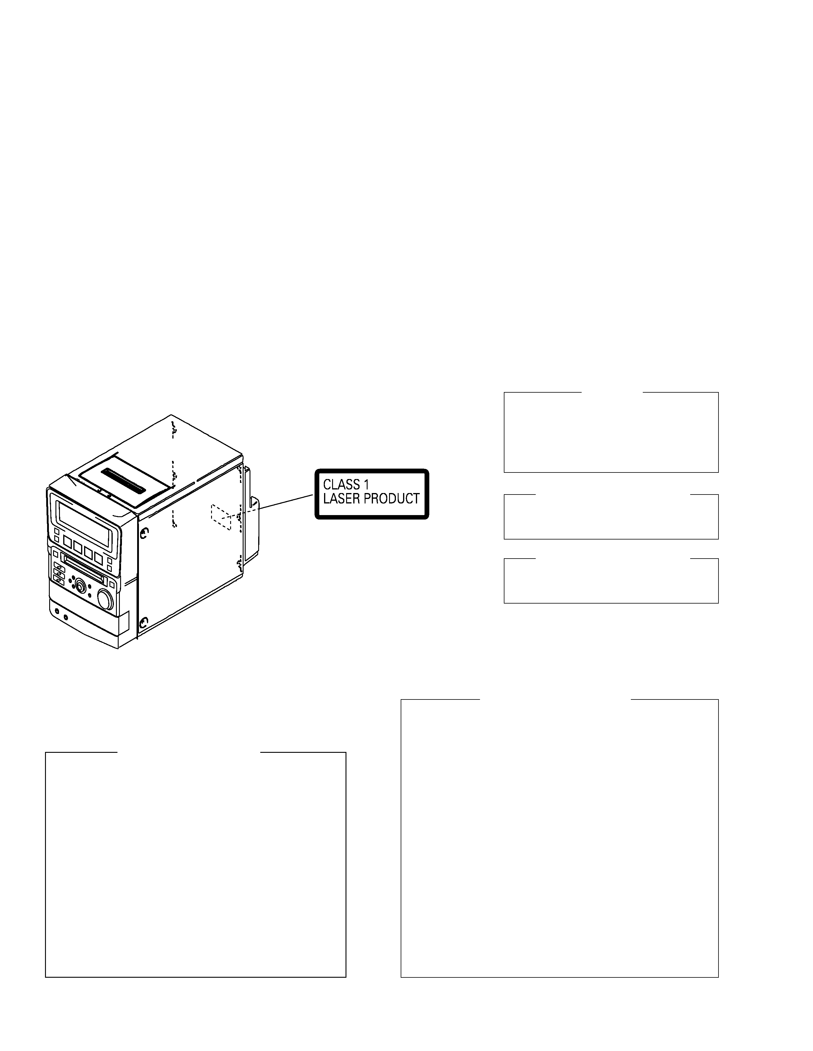
LABEL CHECK
Additional Laser Caution
of CD PLAYER
1. Laser Interlock Mechanism
The position of the switch for detecting loading state is
detected by the system microprocessor, and the design
prevents laser diode oscillation when the switch is
pressed physically.
Thus, the interlock will no longer function if the switch is
released physically and deliberatery.
Laser diode oscillation will continue, if pin 33 of
CXA1782BQ (IC803) on the CD UNIT is connected to
GND, or else the terminals of Q802 are shorted to each
other (fault condition).
2. When the cover is opened, close viewing of the
objective lens with the naked eye will cause exposure
to a Class 1 laser beam.
1. SAFETY INFORMATION
This service manual is intended for qualified service technicians ; it is not meant for the casual do-it-
yourselfer. Qualified technicians have the necessary test equipment and tools, and have been trained
to properly and safely repair complex products such as those covered by this manual.
Improperly performed repairs can adversely affect the safety and reliability of the product and may
void the warranty. If you are not qualified to perform the repair of this product properly and safely, you
should not risk trying to do so and refer the repair to a qualified service technician.
IMPORTANT
THIS PIONEER APPARATUS CONTAINS
LASER OF CLASS 1.
SERVICING OPERATION OF THE APPARATUS
SHOULD BE DONE BY A SPECIALLY
INSTRUCTED PERSON.
LASER DIODE CHARACTERISTICS
OF CD PLAYER
MAXIMUM OUTPUT POWER: 5 mW
WAVELENGTH: 760 - 800 nm
LASER DIODE CHARACTERISTICS
OF MD RECORDER
MAXIMUM OUTPUT POWER: 40 mW
WAVELENGTH: 775 - 800 nm
Control method of the current through a laser diode.
The resistor R166 on the MD MOUNT ASSY (For MD mechanism
assembly) are for the limiting of current through a laser diode.
Control method of the laser output power
The laser pick-up assembly provide the photo-diodes and APC
(Auto Power Control) circuit.
The photo-diode detect output of the laser diode then IC201 control
the APC circuit according to the signal voltage of the photo-diode via
IC101.
Laser Interlock Switch
The loading position detect switch is set to " LOAD ON " position,
IC201 get the " LOAD " signal, and hand the laser " LDON " signal to
APC (Auto Power Control) circuit of the Laser pick-up assembly.
Then a laser diode can be lighted when the " LOAD "signal is "
LOAD ON " position.
Additional Laser Caution
of MD RECORDER