ORDER NO.
PIONEER CORPORATION 4-1, Meguro 1-chome, Meguro-ku, Tokyo 153-8654, Japan
PIONEER ELECTRONICS (USA) INC. P.O. Box 1760, Long Beach, CA 90801-1760, U.S.A.
PIONEER EUROPE NV Haven 1087, Keetberglaan 1, 9120 Melsele, Belgium
PIONEER ELECTRONICS ASIACENTRE PTE. LTD. 253 Alexandra Road, #04-01, Singapore 159936
PIONEER CORPORATION 2002
RRV2639
T ZZM JULY 2002 Printed in Japan
S-HTD5
S-HTD5
XJC/E
S-HTD5 XJC/NC
SPEAKER SYSTEM
FOR PRECAUTION OF
REASSEMBLY AND DISASSEMBLY
The cosmetic baffle is attached to the cabinet by its bosses. To
detach it, pry it open by inserting a flat blade screwdriver into
lower slot. To attach it, press it to the baffle.
The woofer is attatched to the baffle by 4 external screws. To
detach it, unfasten those screws. When attaching it, face its ter-
minal downward.
The tweeter is attached to the baffle by 2 external screws. To
detach it, unfasten those screws. When attaching it, face its ter-
minal downward.
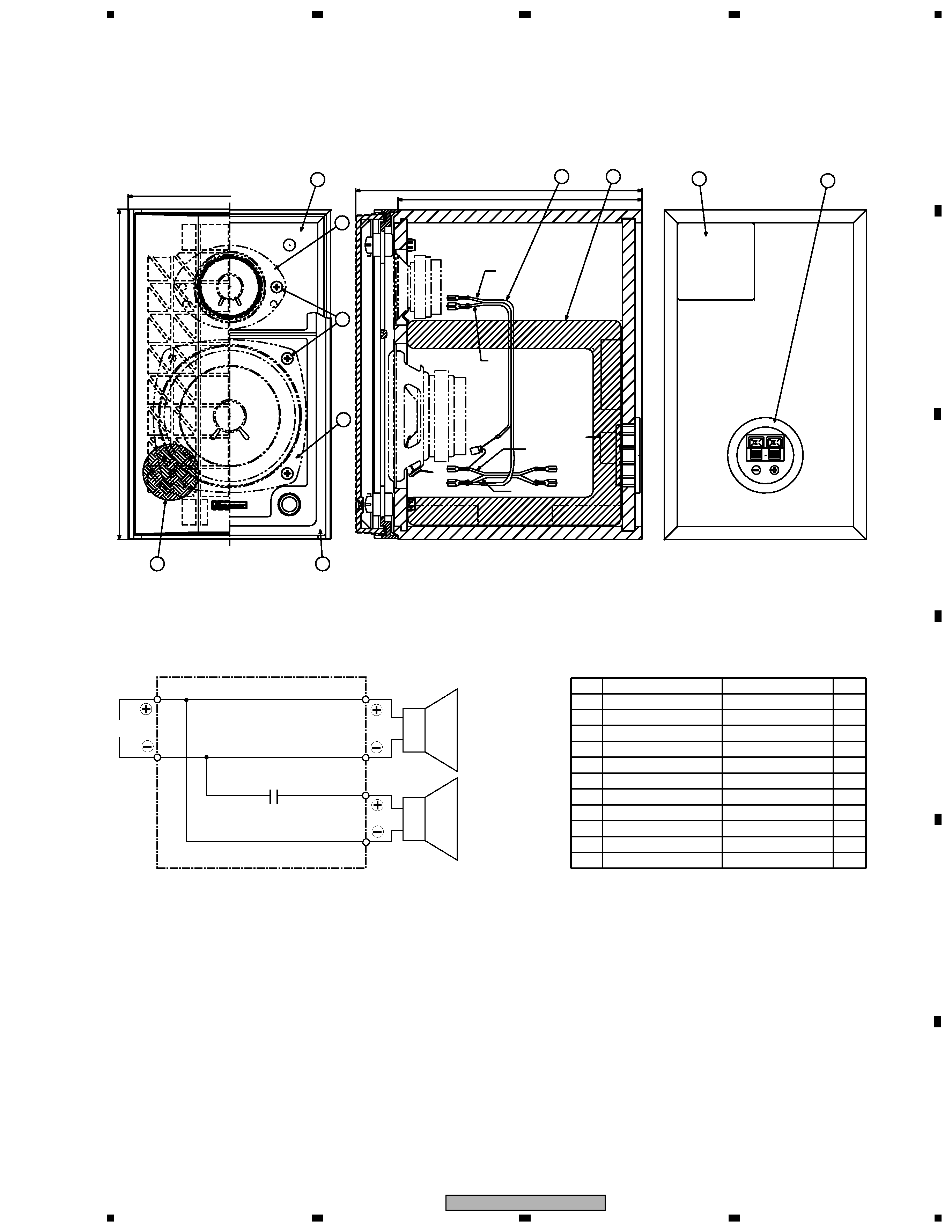
(Front SP)
The woofer is attached to the rear baffle by 4 external screws.
To detach it, unfasten those screws. When attaching it, face its
terminal rightward.
(Sub Woofer)
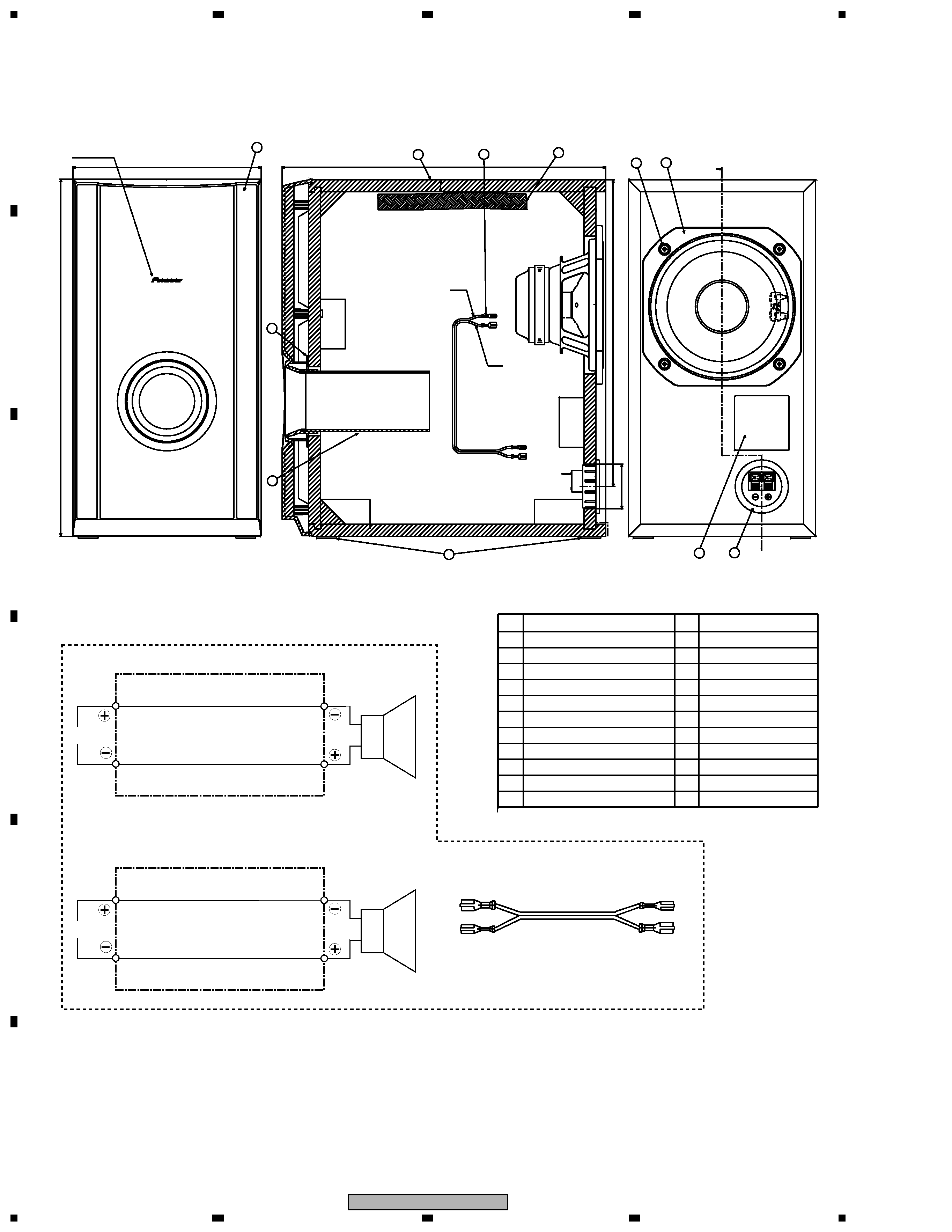
The grille Assy is attached to the cabinet by 8 screws.
To detach it, unfasten those screws.
The speaker unit, together with the grille Assy, is atached to the
cabinet by 4 external screws. To detach it, unfasten those
screws. To detach it, first remove the cabinet. Then remove the
speaker unit. When attaching it, face its terminal toward the
input terminal.
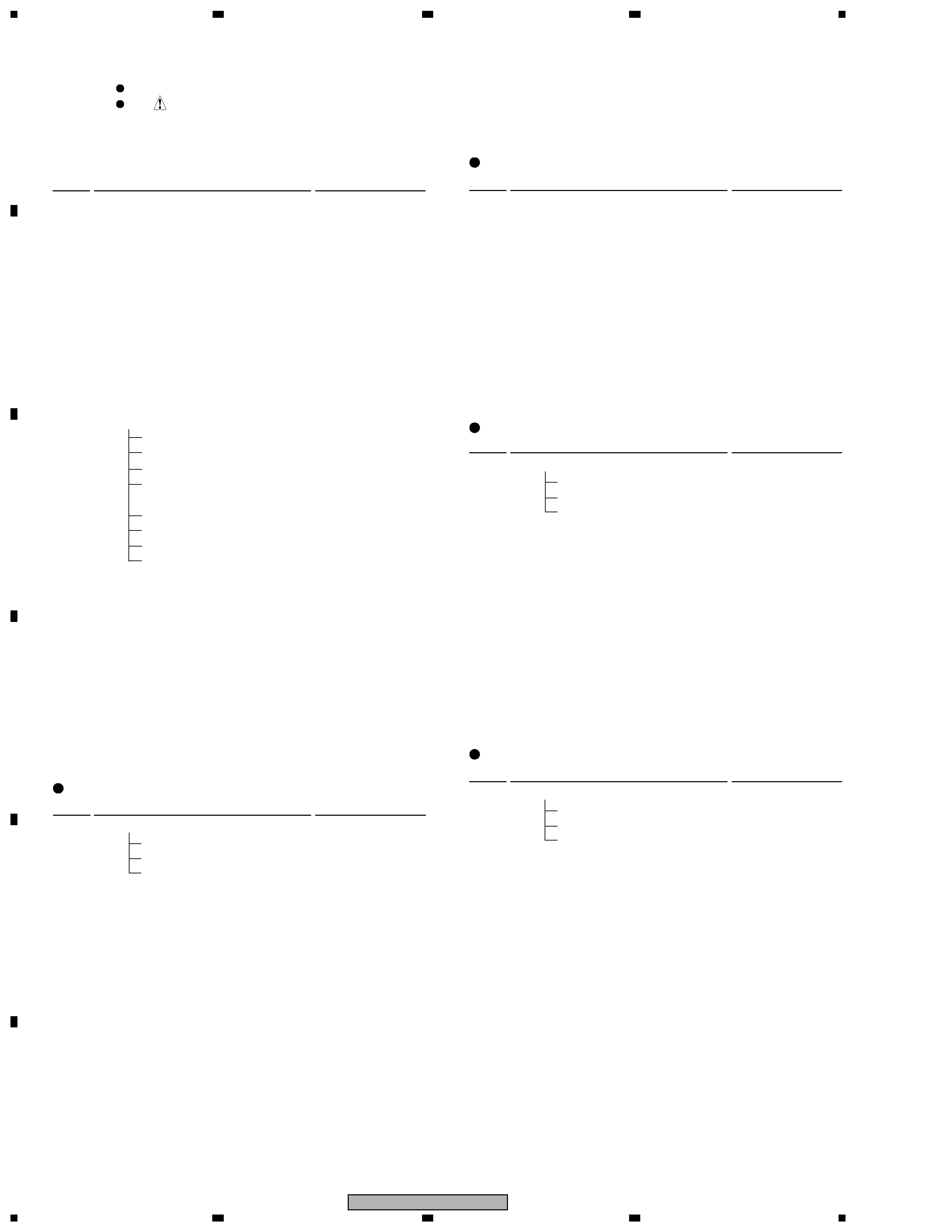
(Center SP)
The grille Assy is attached to the cabinet by 4 screws. To detach
it, unfasten those screws.
The speaker unit, together with the grille Assy, is attached to
the cabinet by 4 external screws. To detach it, unfasten those
screws. To detach it, first remove the cabinet. Then remove the
speaker unit. When attaching it, face its terminal toward the
input terminal.
(Surround Speaker)
Center
Sub Woofer
Front
Surround