ORDER NO.
PIONEER CORPORATION 4-1, Meguro 1-chome, Meguro-ku, Tokyo 153-8654, Japan
PIONEER ELECTRONICS SERVICE, INC. P.O. Box 1760, Long Beach, CA 90801-1760, U.S.A.
PIONEER EUROPE NV Haven 1087, Keetberglaan 1, 9120 Melsele, Belgium
PIONEER ELECTRONICS ASIACENTRE PTE. LTD. 253 Alexandra Road, #04-01, Singapore 159936
PIONEER CORPORATION 2000
c
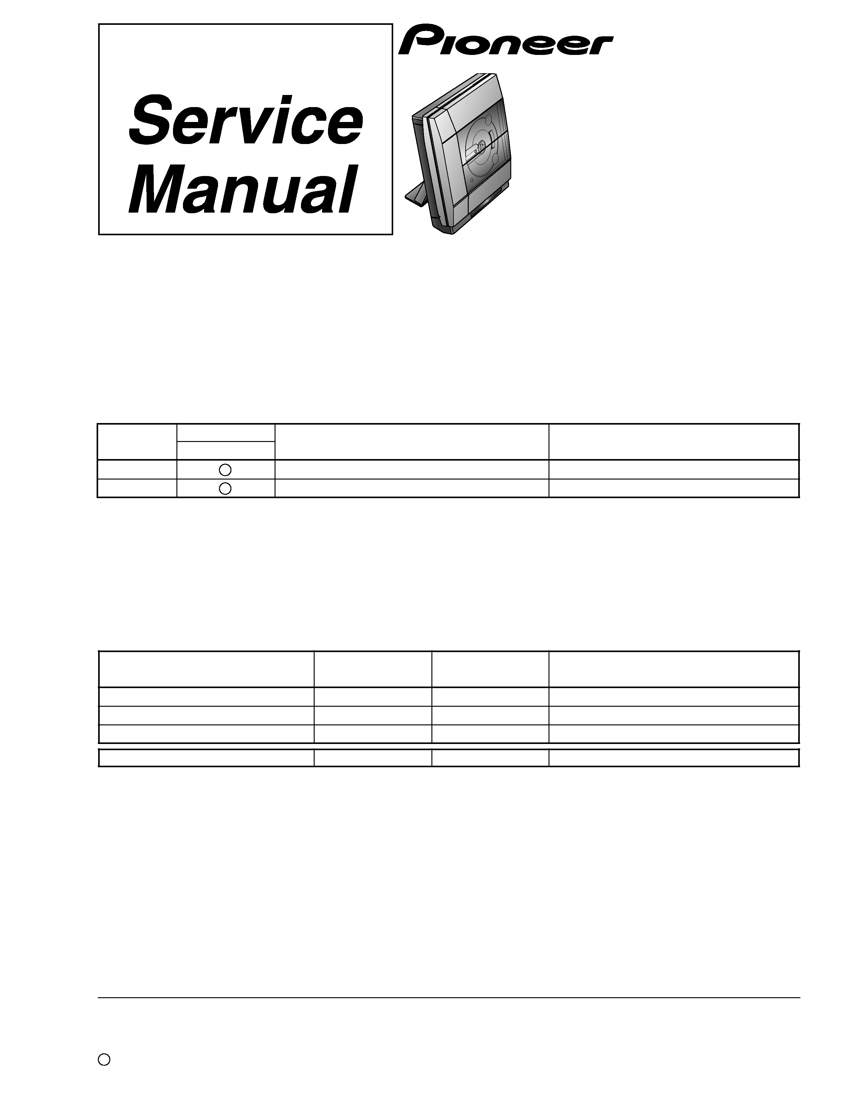
XC-NS3V
RRV2381
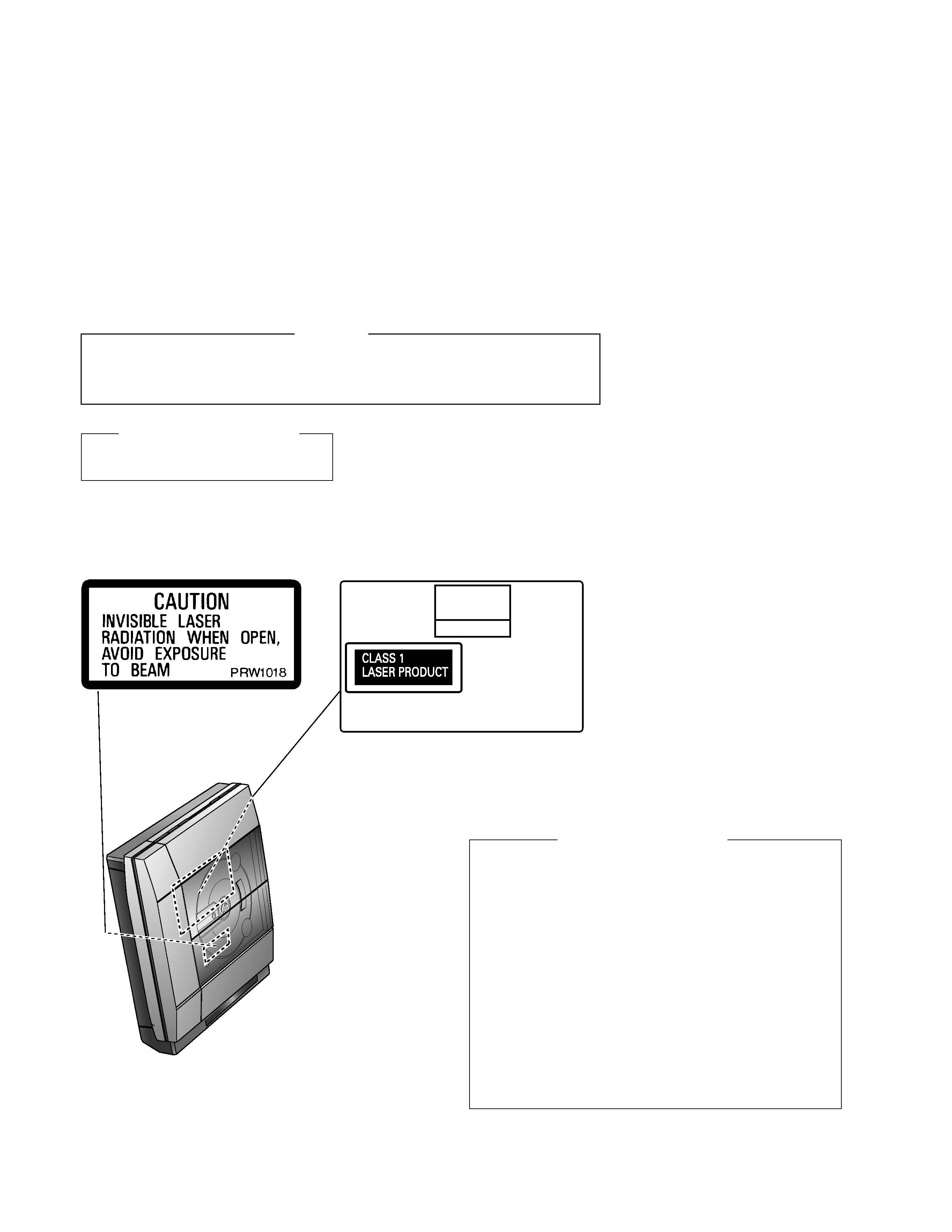
1. SAFETY INFORMATION ...................................... 2
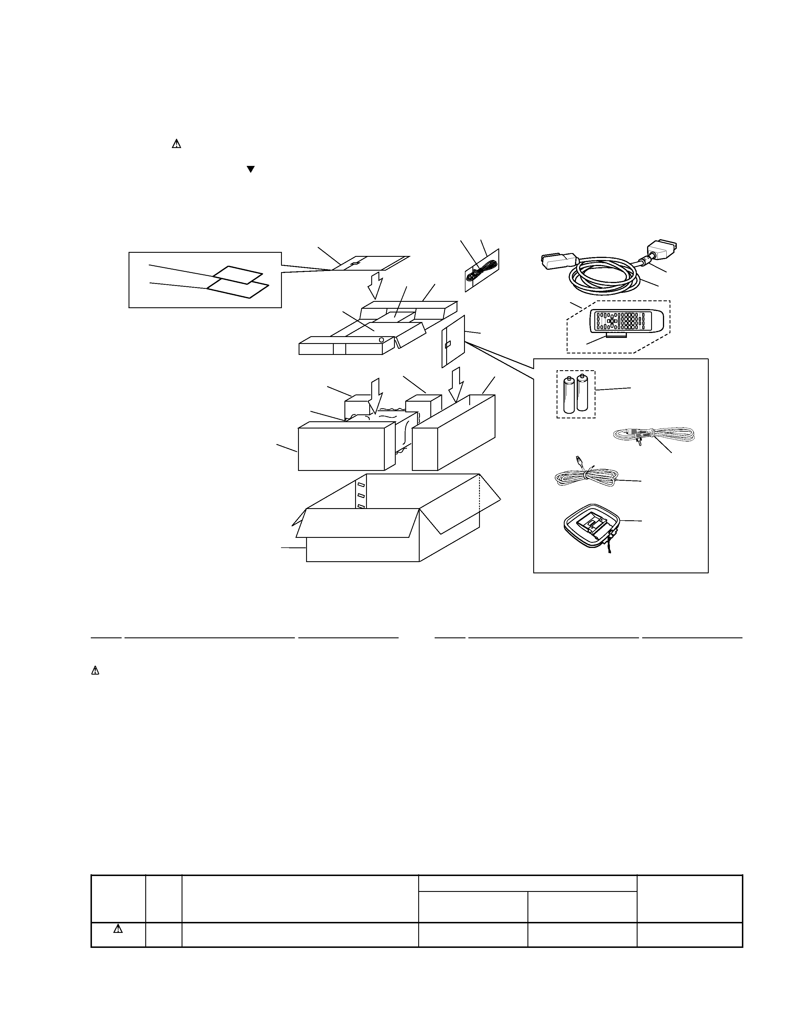
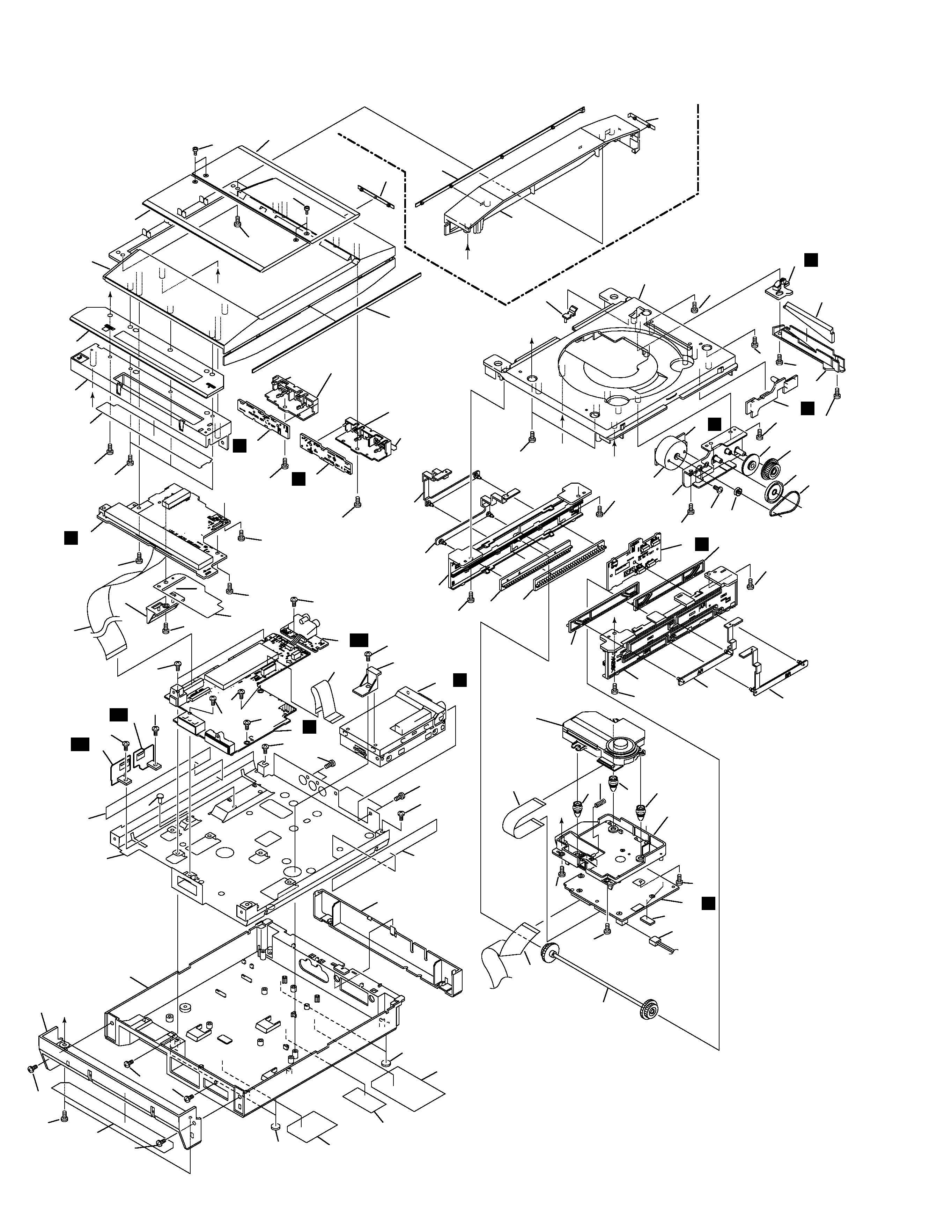
2. EXPLODED VIEWS AND PARTS LIST ............... 3
3. BLOCK DIAGRAM AND SCHEMATIC DIAGRAM ..... 6
4. PCB CONNECTION DIAGRAM ......................... 20
5. PCB PARTS LIST ............................................... 28
6. ADJUSTMENT .................................................... 32
CONTENTS
7. GENERAL INFORMATION ................................ 35
7.1 DIAGNOSIS .................................................. 35
7.1.1 DISASSEMBLY ...................................... 35
7.1.2 SINGLE OPERATION METHOD ............ 38
7.2 PARTS .......................................................... 39
7.2.1 IC ............................................................ 39
7.2.2 DISPLAY ................................................. 53
8. PANEL FACILITIES AND SPECIFICATIONS ....... 54
T ZZK SEPT. 2000 Printed in Japan
STEREO CD/VCD TUNER
THIS MANUAL IS APPLICABLE TO THE FOLLOWING MODEL(S) AND TYPE(S).
¶ This product is a system(s) component.
This product does not function properly independently ; to avoid malfunctions, be
sure to connect it to the prescribed system component(s), otherwise damage may
result.
¶ Please connect it to the STEREO POWER AMPLIFIER M-NS1, for adjustment and
operation inspection.
Type
Model
Power Requirement
Remarks
XC-NS3V
ZBDXJ
DC power supplied from other system component
ZLXJ/NC
DC power supplied from other system component
Component
Model
Service manual
Remarks
STEREO CD/VCD TUNER
XC-NS3V
RRV2381
This manual.
STEREO POWER AMPLIFIER
M-NS1
RRV2349 (RRV2321)
SPEAKER SYSTEM
S-NS1-LRW
RRV2371
MINIDISC RECORDER
MJ-NS1
RRV2363