ORDER NO.
PIONEER ELECTRONIC CORPORATION 4-1, Meguro 1-Chome, Meguro-ku, Tokyo 153-8654, Japan
PIONEER ELECTRONICS SERVICE, INC. P.O. Box 1760, Long Beach, CA 90801-1760, U.S.A.
PIONEER ELECTRONIC NV Haven 1087, Keetberglaan 1, 9120 Melsele, Belgium
PIONEER ELECTRONICS ASIACENTRE PTE. LTD. 253 Allexandra Road, #04-01, Singapore 159936
PIONEER ELECTRONIC CORPORATION 2001
c
RRV2442
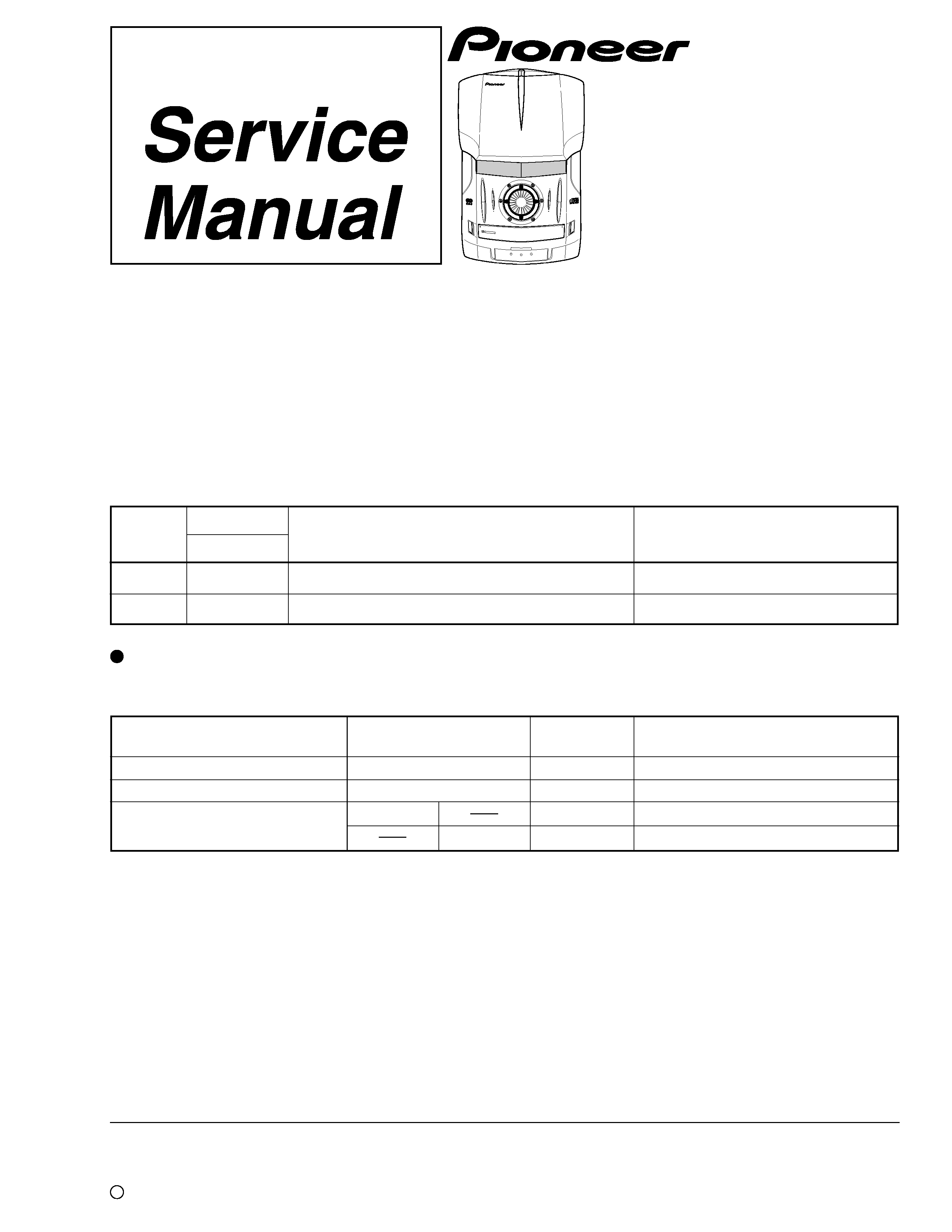
XC-IS22CD
1. SAFETY INFORMATION ....................................... 2
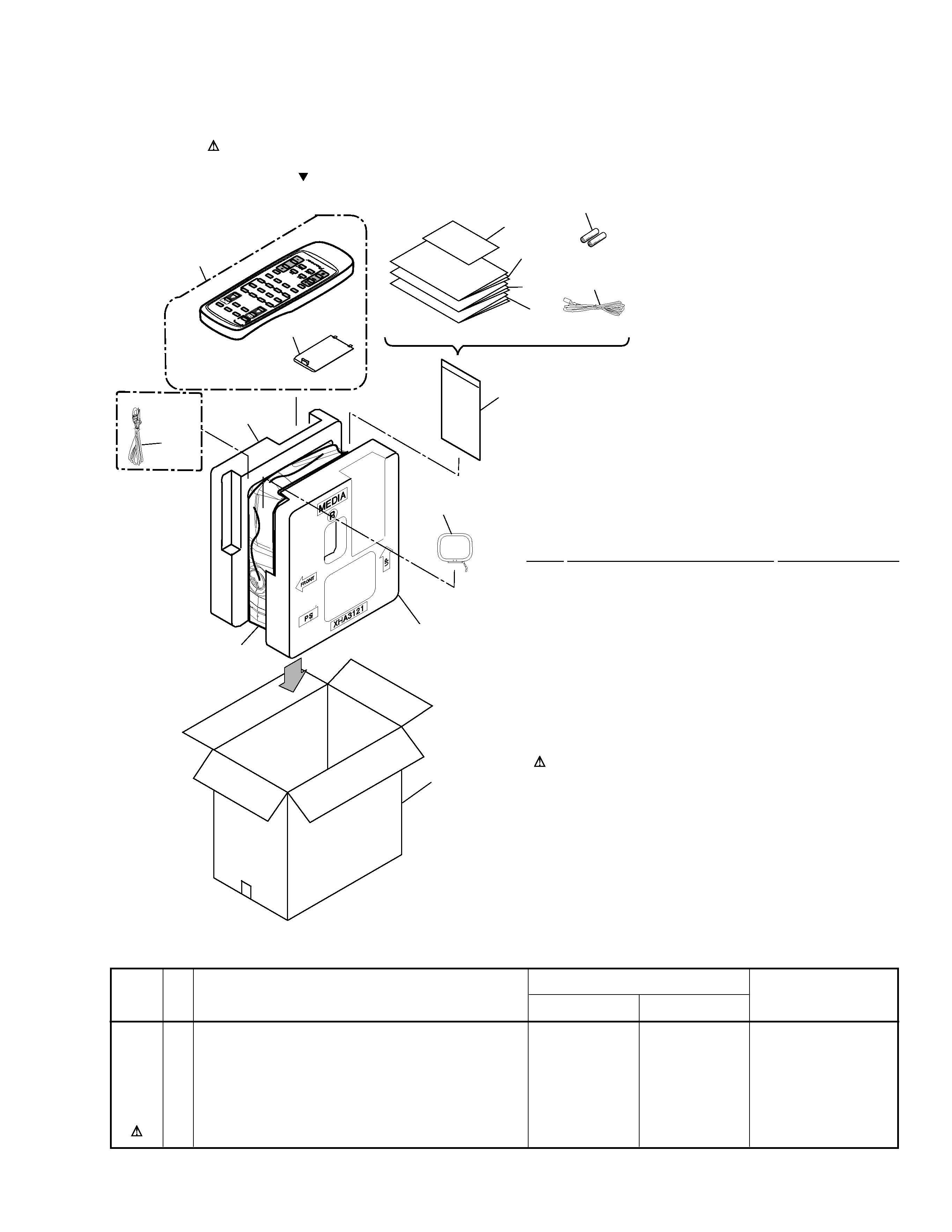
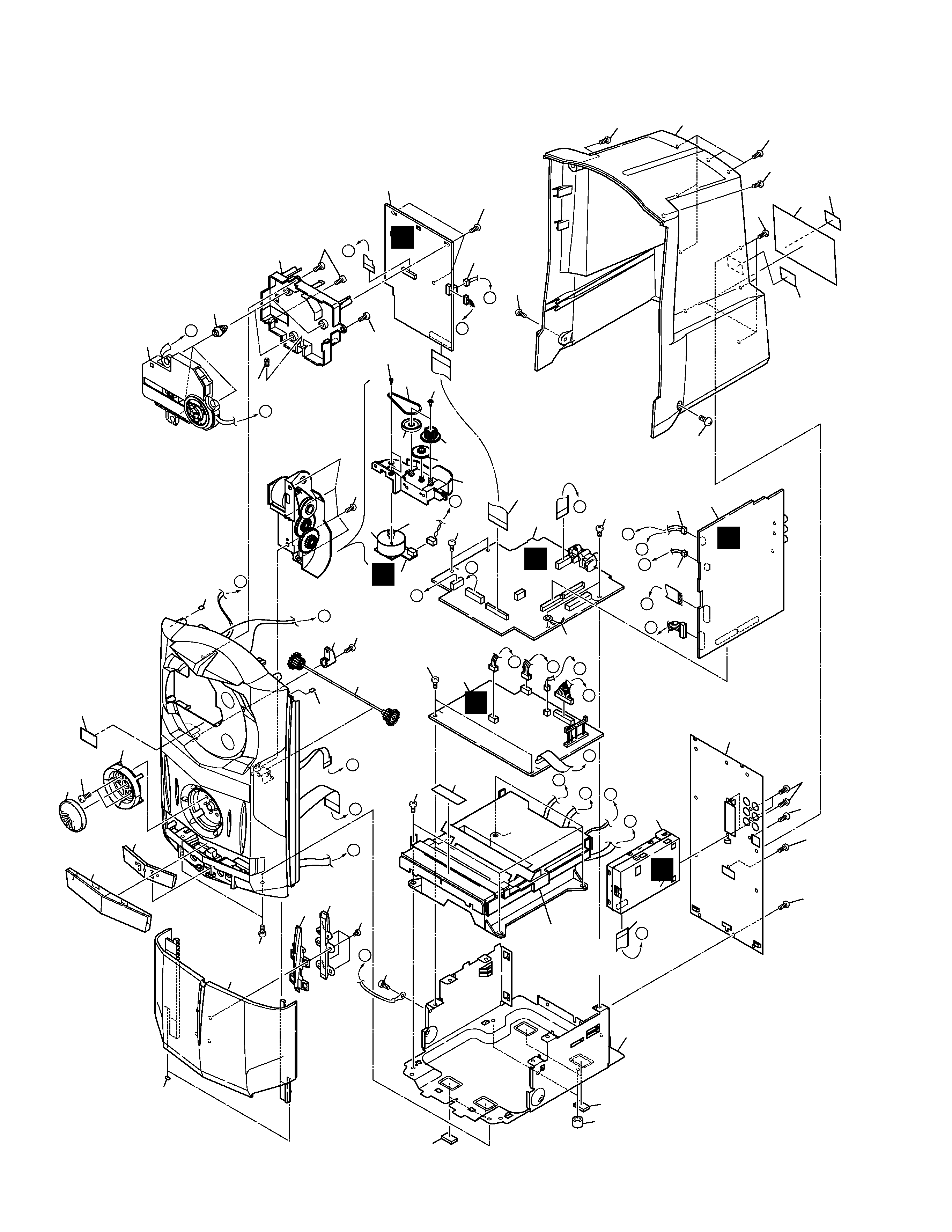
2. EXPLODED VIEWS AND PARTS LIST ................. 3
3. BLOCK DIAGRAM AND SCHEMATIC DIAGRAM 12
4. PCB CONNECTION DIAGRAM ........................... 32
5. PCB PARTS LIST ................................................ 44
6. ADJUSTMENT ..................................................... 49
7. GENERAL INFORMATION .................................. 55
CONTENTS
7.1 DIAGNOSIS ................................................... 55
7.1.1 SEQUENCE AFTER THE POWER ON . 55
7.1.2 SINGLE OPERATION METHOD ........... 56
7.1.3 TROUBLE SHOOTING .......................... 58
7.1.4 DISASSEMBLY ..................................... 59
7.2 PARTS .......................................................... 64
7.2.1 IC ........................................................... 64
8. PANEL FACILITIES AND SPECIFICATIONS ....... 72
T ZZY APR. 2001 Printed in Japan
THIS MANUAL IS APPLICABLE TO THE FOLLOWING MODEL(S) AND TYPE(S).
CD TUNER DECK
Remarks
Type
Model
XC-IS22CD
Power Requirement
ZYXJ
O
DC power supply from other system
ZVXJ
O
DC power supply from other system
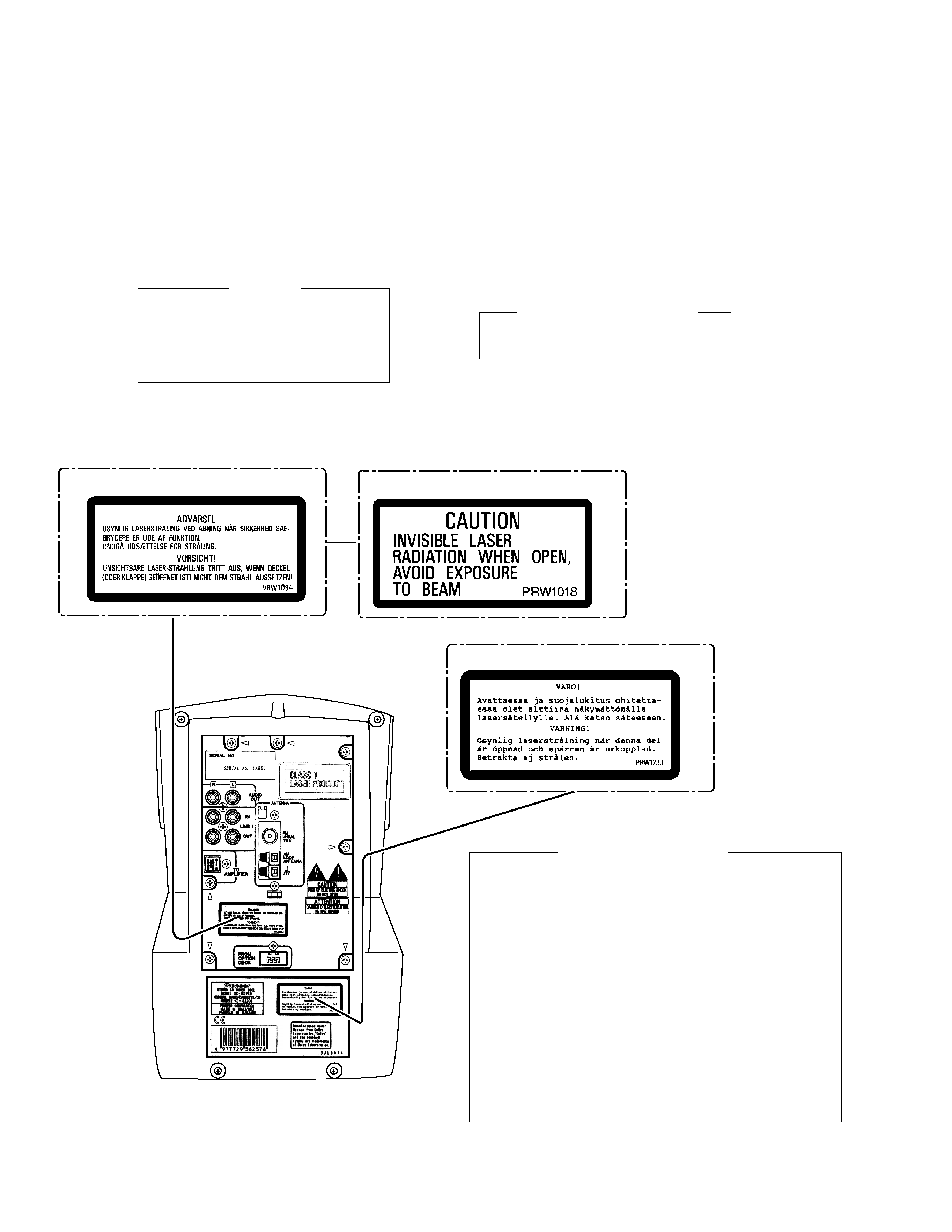
This product is a system(s) component.
This product does not function properly when independent; to avoid malfunctions, be sure
to connect it to the prescribed system component(s), otherwise damage may result.
CD TUNER DECK
XC-IS22CD
RRV2442
This service manual
STEREO POWER AMPLIFIER
M-IS22
RRV2445
System
Component
Remarks
ENHANCE
BALANCE
TREBLE
BASS
CD
TUNER
TAPE
LINE1.2
FRONT LOADING TRAY MECHANISM DECK
TAPE
OPEN/CLOSE
0
S
T.
M
E
M
O
R
Y
· S
TO
P
7
6
PL
AY
/P
A
U
S
E
R
E
V
E
R
S
E
M
O
D
E
D
IS
P/
RD
S
2 V
OL. / JOG + 3
SE
T
T
IM
E
R
/
C
L
O
C
K
A
D
J
A
SE
S
RE
C/
ST
O
P
1
·4
· T
UN
ING
+ TU
NIN
G
· ¢
· ¡
OPEN/
STEREO CD TUNER DECK XC-IS22CD
CLOSE
LINE2IN
OPTICAL DIGITAL OUT LINE2 OUT
DOLBY NR
ON/OFF(DEMO)
DOLBY B NR
SPEAKER SYSTEM
S-IS22
S-IS22S
RRV2450
RRV2451
Service Manual