ORDER NO.
PIONEER ELECTRONIC CORPORATION 4-1, Meguro 1-Chome, Meguro-ku, Tokyo 153-8654, Japan
PIONEER ELECTRONICS SERVICE, INC. P.O. Box 1760, Long Beach, CA 90801-1760, U.S.A.
PIONEER ELECTRONIC (EUROPE) N.V. Haven 1087, Keetberglaan 1, 9120 Melsele, Belgium
PIONEER ELECTRONICS ASIACENTRE PTE. LTD. 253 Allexandra Road, #04-01, Singapore 159936
PIONEER ELECTRONIC CORPORATION 1999
c
RRV2149
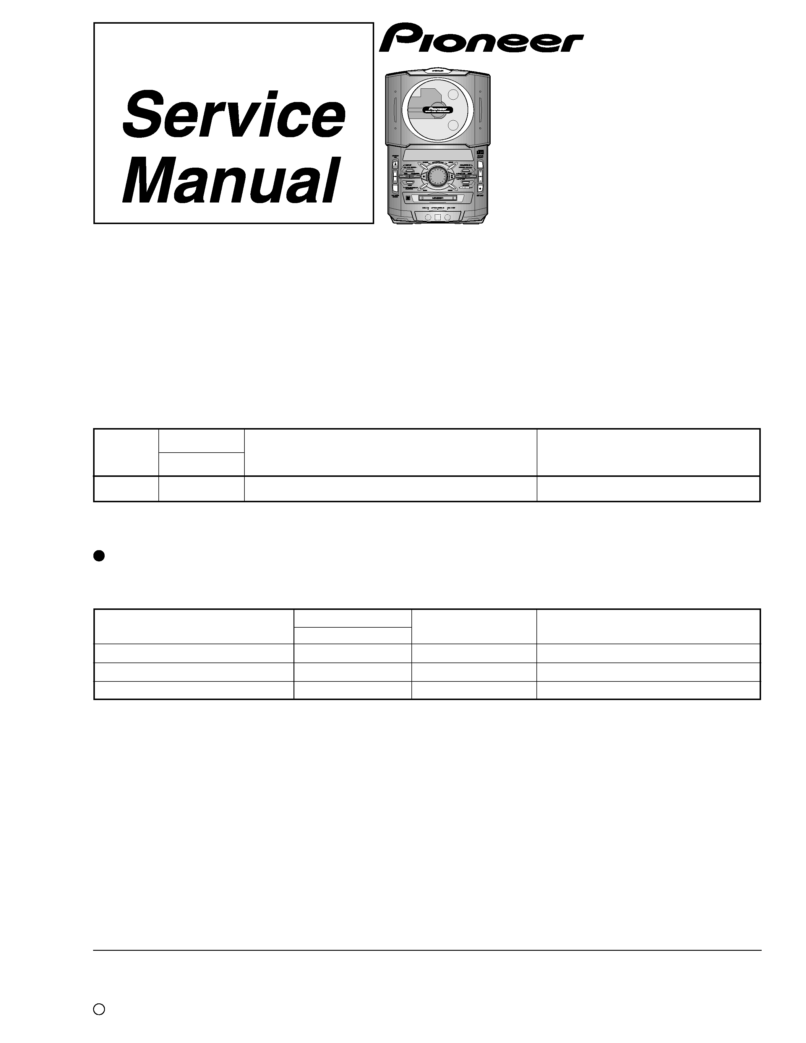
XC-IS21MD
1. SAFETY INFORMATION ....................................... 2
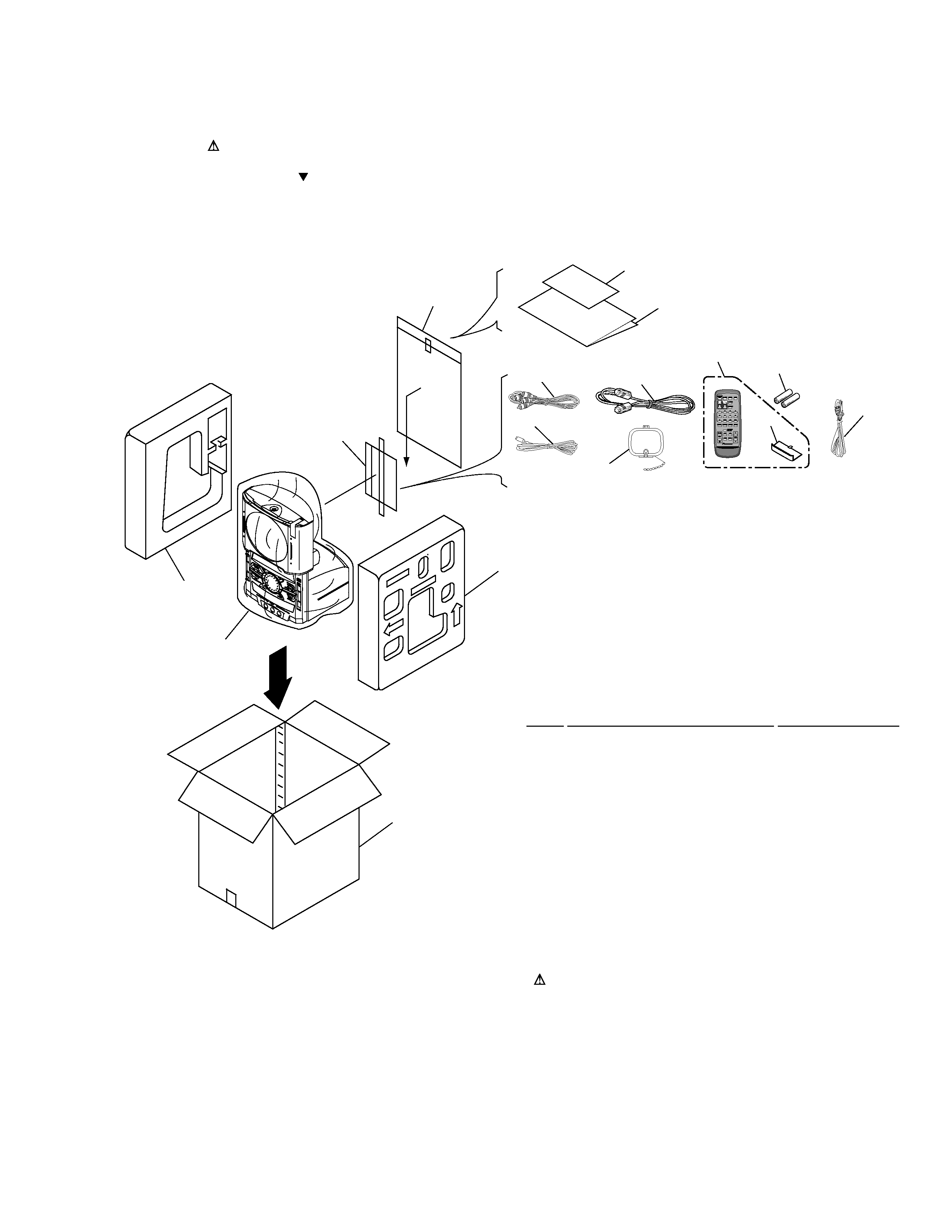
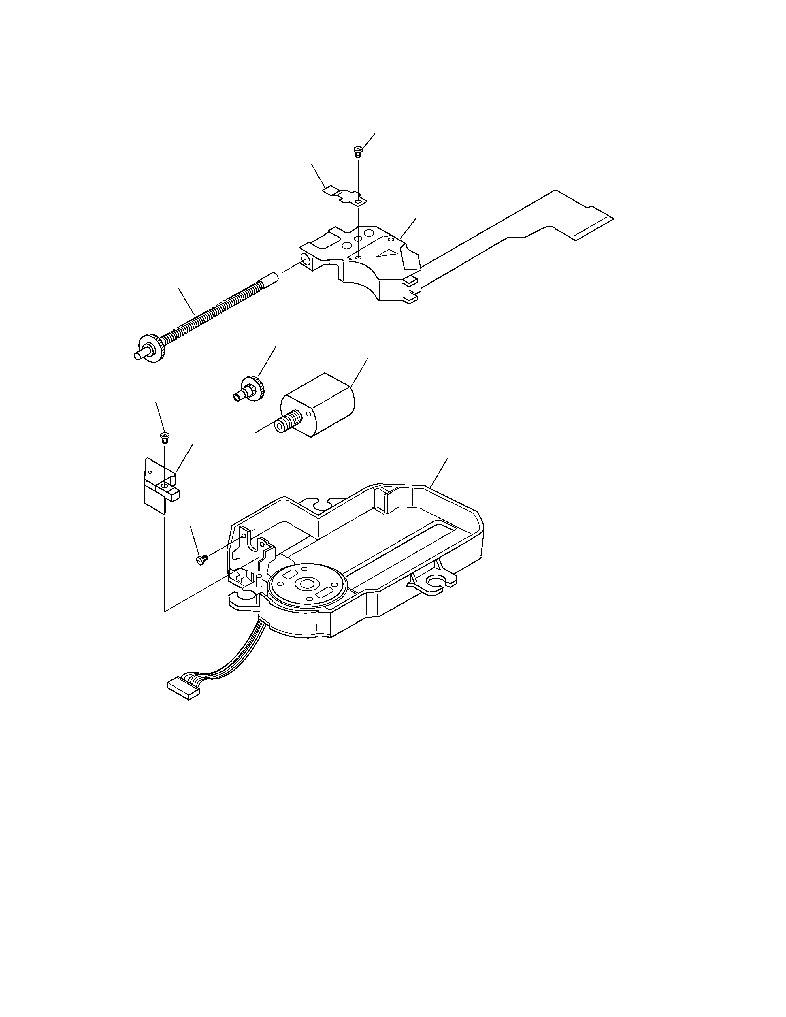
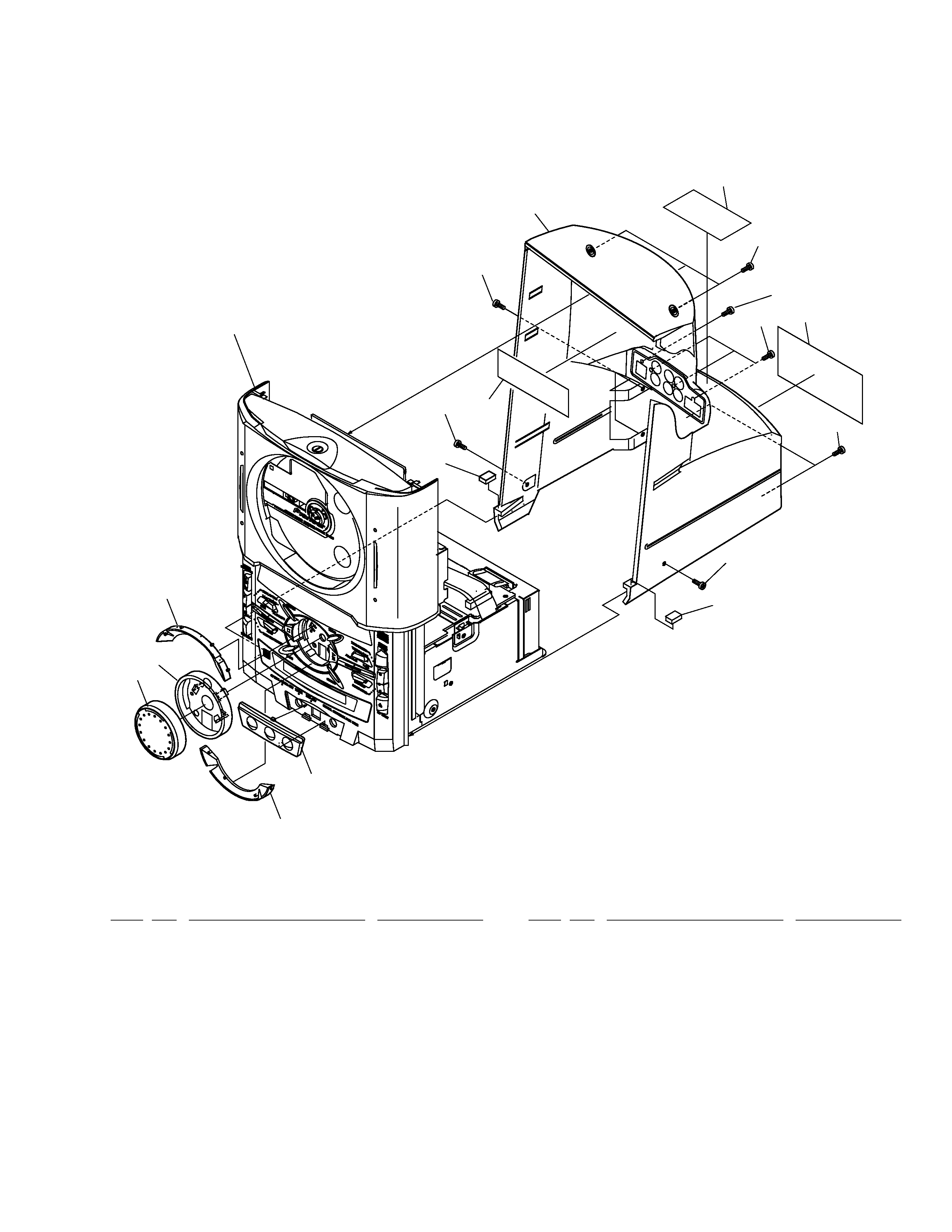
2. EXPLODED VIEWS AND PARTS LIST ................. 3
3. BLOCK DIAGRAM AND SCHEMATIC DIAGRAM 14
4. PCB CONNECTION DIAGRAM ........................... 38
5. PCB PARTS LIST ................................................ 52
6. ADJUSTMENT ..................................................... 57
7. GENERAL INFORMATION .................................. 68
CONTENTS
7.1DIAGNOSIS .................................................... 68
7.1.1 SINGLE OPERATION METHOD ........... 68
7.1.2 SEQUNCE AFTER THE POWER ON ... 70
7.1.3 DETAILS OF ERROR DISPLAY ........... 71
7.1.4 DISASSEMBLY ..................................... 74
7.1.5 PCB LOCATION .................................... 80
7.2 PARTS ........................................................... 81
7.2.1 IC .......................................................... 81
8. PANEL FACILITIES AND SPECIFICATIONS ....... 96
T ZZY MAY 1999 Printed in Japan
THIS MANUAL IS APPLICABLE TO THE FOLLOWING MODEL(S) AND TYPE(S).
CD MD TUNER
Remarks
Type
Model
XC-IS21MD
Power Requirement
ZUCXJ
O
DC power supply from other system
This product is a system(s) component.
This product does not function properly when independent; to avoid malfunctions, be sure
to connect it to the prescribed system component(s), otherwise damage may result.
CD MD TUNER
XC-IS21MD
RRV2149
This service manual
STEREO POWER AMPLIFIER
M-IS21
RRV2143
SPEAKER SYSTEM
S-IS21
RRV2141
System
IS-21MD
Component
Service Manual
Remarks