2
XC-F10
WARNING!
Lithium batteries. Danger of explo-
sion. Replacement must be done by
qualified personnel and only by fol-
lowing the instructions given in the
service manual.
This warning is stated on the product or
in the operating instructions. When replac-
ing the lithium batteries, follow the note
below.
Dispose of the used battery promptly.
Keep away from children. Do not disas-
semble and do not dispose of in fire.
The battery used in this device may present
a fire or chemical hazard if mistreated. Do
not recharge,
disassemble,
heat above
100
°C or incinerate. Replace only with the
same Part Number. Use of another battery
may present a risk of fire or explosion.
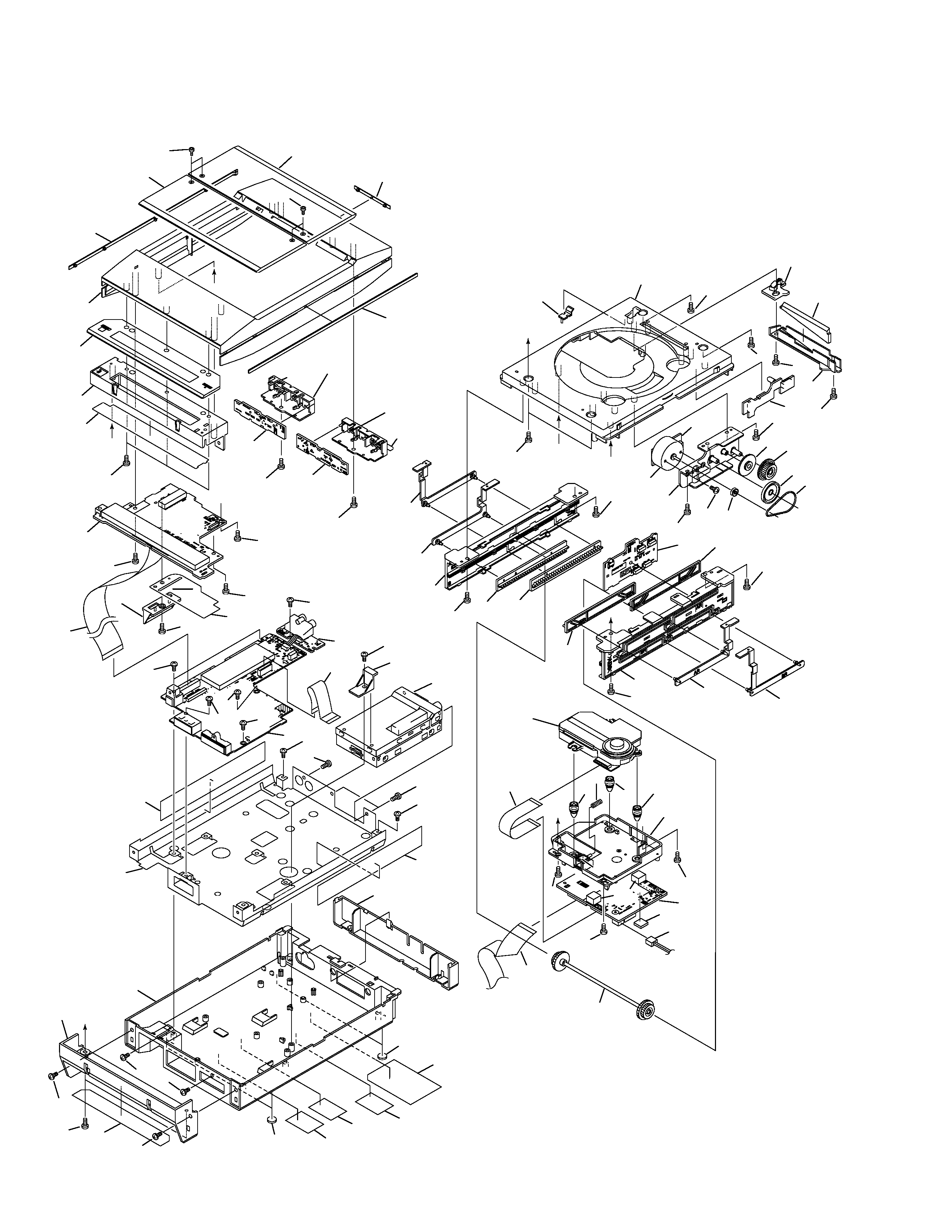
Note: The lithium battery installation po-
sition is shown in the exploded views.
ADVARSEL!
Lithiumbatteri
- Eksplosionsfare ved
fejlagtig håndtering. Udskiftning må kun
ske med batteri af samme fabrikat og
type. Levér det brugte batteri tilbage til
leverandøren.
Denne advarsel or angivet på produktet
eller i brugsvejledningen. Ved udskiftning
af lithium batterierne følges nedenstående
anveisning.
Batterierne må kun udskiftes med batteri-
er af samme type og mærke.
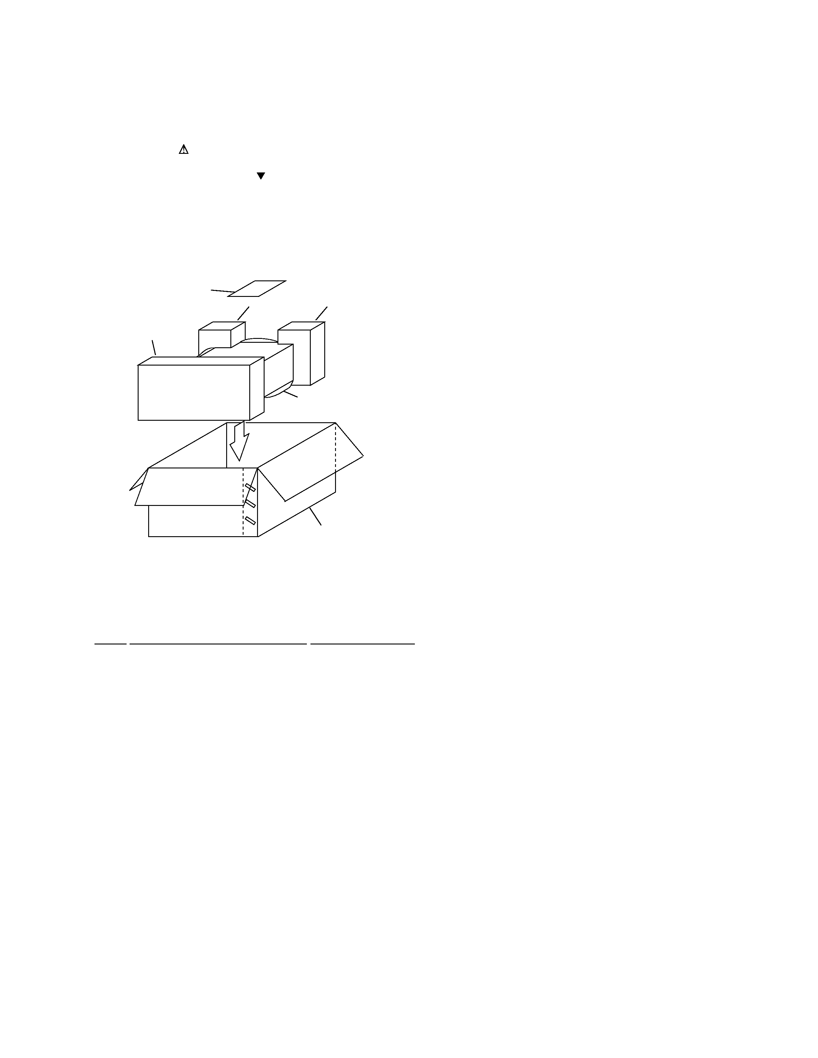
1. SAFETY INFORMATION
LITHIUM BATTERY NOTICE
LABEL CHECK
1. Laser Interlock Mechanism
The position of the switch (S5907) for detecting loading
state is detected by the system microprocessor, and the
design prevents laser diode oscillation when the switch
(S5907) is not on CLOSE terminal side (CDO/C signal is
high level).
Thus, the interlock will no longer function if the switch
(S5907) deliberately set to CLOSE terminal side (low
level).
The interlock also does not function in the test mode
.
Laser diode oscillation will continue, if pin 9 of TA2150FN
(IC1101) on the SELF-CHACK CD ASSY is connected to
GND, or pin 10 is connected to low level (ON), or else the
terminals of Q1101 are shorted to each other (fault
condition).
2. When the DOOR WINDOW is removed, close viewing of
the objective lens with the naked eye will cause exposure
to a Class 1 laser beam.
: Refer to page 29.
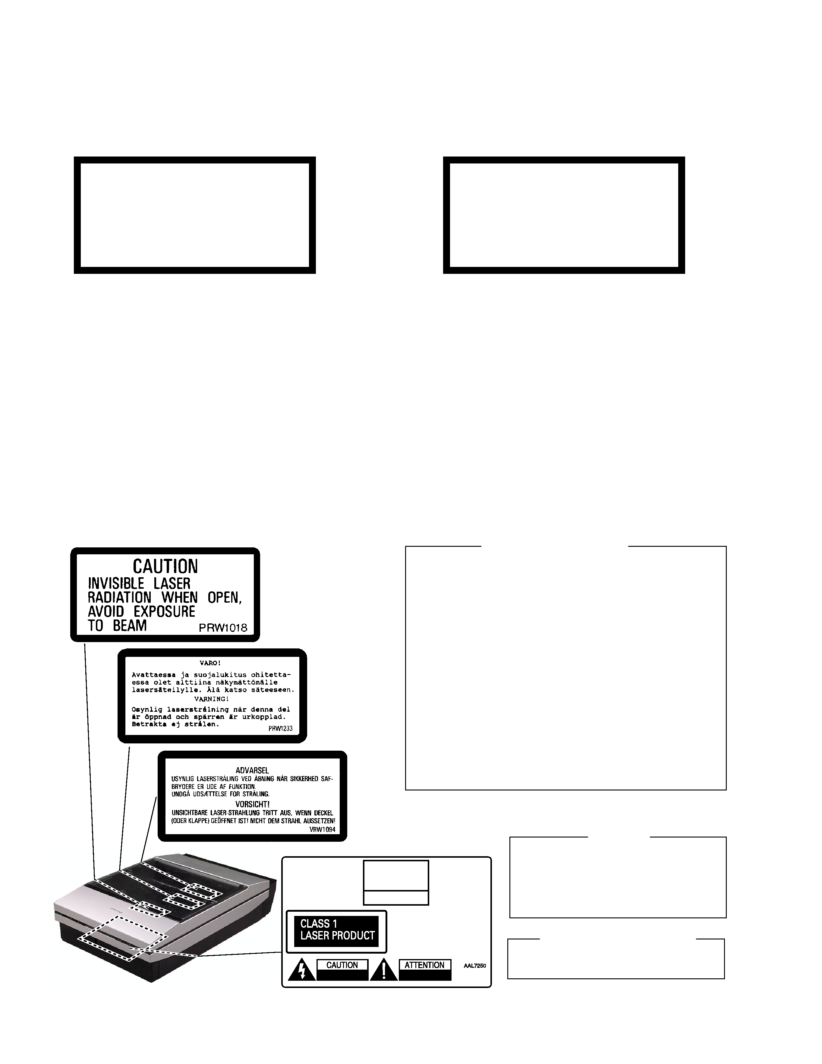
Additional Laser Caution
IMPORTANT
THIS PIONEER APPARATUS CONTAINS
LASER OF CLASS 1.
SERVICING OPERATION OF THE APPARATUS
SHOULD BE DONE BY A SPECIALLY
INSTRUCTED PERSON.
LASER DIODE CHARACTERISTICS
MAXIMUM OUTPUT POWER: 5 mW
WAVELENGTH: 780 785 nm