VSX-D511-K
5
5
678
56
7
8
C
D
F
A
B
E
1. SPECIFICATIONS
Î
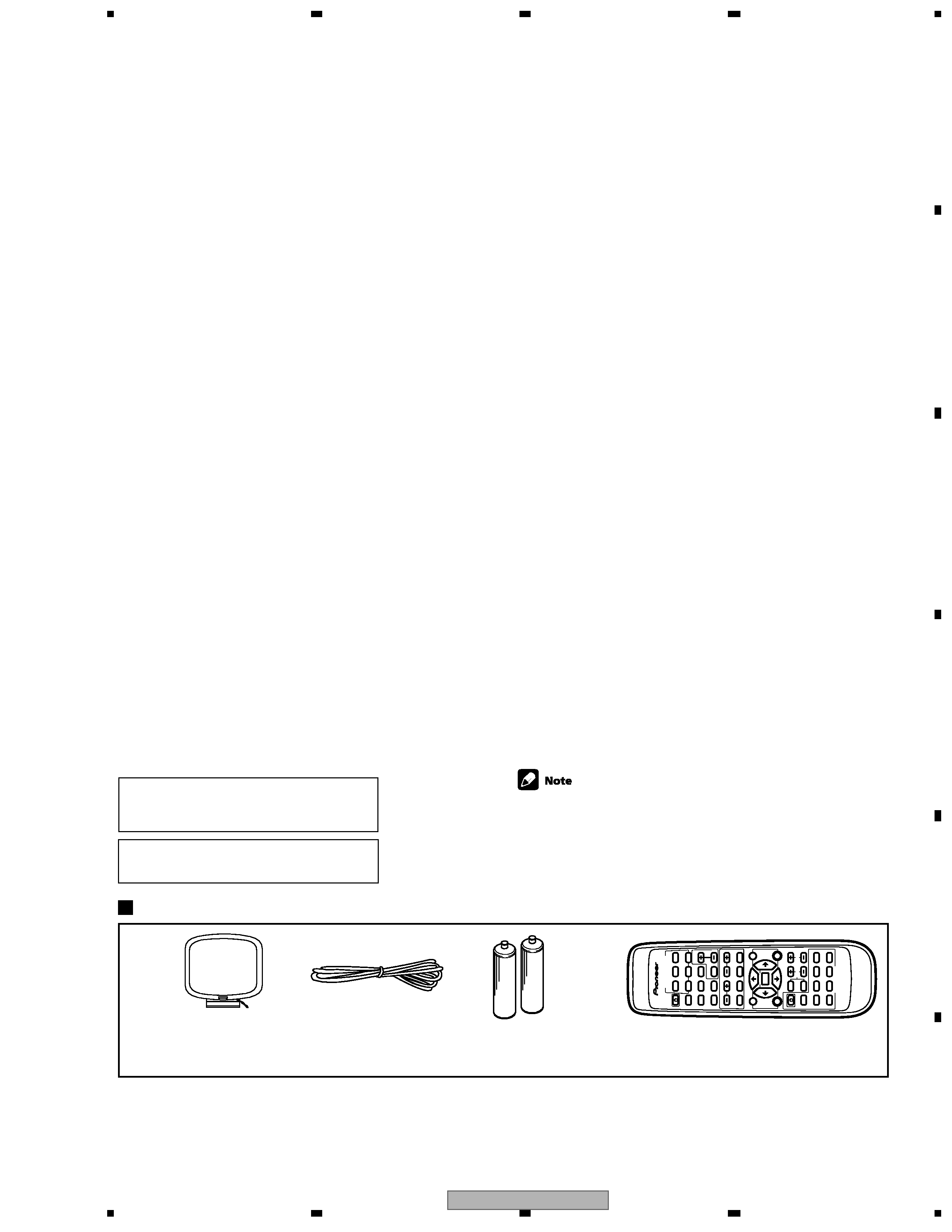
Accessories
Remote control unit
(XXD3039)
AM loop antenna
(ATB7009)
FM wire antenna
(ADH7005)
AA size IEC R6P
Dry cell batteries (x2)
Amplifier Section
Front .................................... 80 W per channel
(DIN 1kHz, THD 1.0 %, 8
)
Front
Continuous Power Output
..................................................... 80 W per channel
(1kHz, THD 1.0 %, 8
)
Center
......................................... 80 W (1kHz, THD 1.0 %, 8
)
Surround .................... 80 W per channel (1kHz, THD 1.0 %, 8
)
Above specifications are applicable when the power supply is 230V.
Input (Sensitivity/Impedance)
CD, VCR/DVR, CD-R/TAPE/MD, DVD/LD, TV/SAT ... 200 mV/47 k
Frequency Response
CD, VCR/DVR, CD-R/TAPE/MD, DVD/LD,TV/SAT
.................................................................. 5 Hz to 100,000 Hz
dB
Output (Level/Impedance)
VCR/DVR REC, CD-R/TAPE/MD REC .................... 200 mV/2.2 k
Tone Control
BASS ......................................................................
± 6 dB (100 Hz)
TREBLE ..................................................................
± 6 dB (10 kHz)
LOUDNESS ..................................... +9 dB/+9 dB (100 Hz/10 kHz)
Signal-to-Noise Ratio [DIN (Continuous rated power output/50 mW)]
CD, VCR/DVR, CD-R/TAPE/MD,DVD/LD, TV/SAT ............. 88/64 dB
Video Section
Input (Sensitivity/Impedance)
VCR/DVR, DVD/LD, TV/SAT ......................................... 1 Vp-p/75
Output (Level/Impedance)
VCR/DVR ...................................................................... 1 Vp-p/75
Frequency Response
VCR/DVR, DVD/LD,TV/SAT
] MONITOR ........ 5 Hz to 7 MHz dB
Signal-to-Noise Ratio .............................................................. 55 dB
Cross Talk ............................................................................... 55 dB
FM Tuner Section
Frequency Range .......................................... 87.5 MHz to 108 MHz
Usable Sensitivity ....................... Mono:13.2 dBf, IHF (1.3
µV/ 75 )
50 dB Quieting Sensitivity ......................................... Mono: 20.2 dB
Stereo: 38.6 dBf
Signal-to-Noise Ratio ................................. Mono: 73 dB (at 85 dBf)
Stereo: 70 dB (at 85 dBf)
Signal-to-Noise Ratio (DIN) ....................................... Mono: 62 dB
Stereo: 58 dB
Distortion ........................................................ Stereo: 0.5 % (1 kHz)
Alternate Channel Selectivity ................................. 60 dB (400 kHz)
Stereo Separation ...................................................... 40 dB (1 kHz)
Frequency Response ................................. 30 Hz to 15 kHz (
±1 dB)
Antenna Input (DIN) .............................................. 75
unbalanced
AM Tuner Section
Frequency Range ........................................... 531 kHz to 1,602 kHz
Sensitivity (IHF, Loop antenna) ......................................... 350
µV/m
Selectivity ................................................................................ 25 dB
Signal-to-Noise Ratio .............................................................. 50 dB
Antenna ...................................................................... Loop antenna
Miscellaneous
Power Requirements
UK model
European model
...............................................
.........................................
A
AC 220-230 V, 50/60 Hz
C 230 V, 50/60Hz
Power Consumption
....................................................................... 220W
In Standby ............................................................................. 1 W
Dimensions ................................... 420 (W) x 158 (H) x 393 (D) mm
Weight (without package)
kg
.......................................................................... 9.0
Furnished Parts
AM loop antenna ............................................................................ 1
FM wire antenna ............................................................................ 1
Dry cell batteries (AA size IEC R6P) .............................................. 2
Remote control ............................................................................... 1
Operating instructions .................................................................... 1
Specifications and the design are subject to possible modifications
without notice, due to improvements.
+0
3
+0
3
"DTS" ,"ES" and "DTS Digital Surround" are trademarks
of Digital Theater Systems, Inc.
Manufactured under license from Dolby Laboratories.
"Dolby", "Pro Logic II" and the double D symbol 2
are
trademarks of Dolby Laboratorories.
Continuous Power Output (STEREO mode)
INPUT
SELECT
O
R
CD
TV/SA
T
D
VD/LD
RECEIVER
DV
D
D
VD
CONTR
OL
SUB
TITLE
A
UDIO
TEST T
ONE
LEVEL
EFFECT
MENU
DV
D
TUNER
EDIT
RECEI- VER
T
OP
MENU
ST
AND
ARD
STEREO
AD
VANCED
SURR
OUND
INPUT AT
T
FL
DIMMER
MUTE
MASTER V
O
LUME
CD-R/
T
APE/MD
VCR/ DV
R
ENTER
SETUP
A
V
RECEIVER
TUNING
B
A
ND
CLASS
M
PX
DISPLA
Y
CH
SELECT
ST
A
T
ION
MIDNIGHT/ LOUDNESS
TUNER
1
¢
4
¡
78
3