PIONEER VSX-D3S/SD Owner's Manual

Cover page of PIONEER VSX-D3S/SD Owner's Manual

Owner's Manual for PIONEER VSX-D3S/SD, downloadable as a PDF file.

Manual details

  • Immediate download after payment.
  • Delivered as a PDF file.
  • The manual has 40 pages
  • File size: 1.02 MB
  • Available language versions: English
  • Different language versions may vary sligthly in file size and page count.

We guarantee that...

  • our manuals are complete,
  • our manuals are checked with antivirus,
  • We'll issue refund if the manual is damaged, incomplete or unreadable (our refund policy)

Sample pages

Thumbnail of page 1Thumbnail of page 2Thumbnail of page 3Thumbnail of page 4
Thumbnail of page 5Thumbnail of page 6Thumbnail of page 7Thumbnail of page 8
Thumbnail of page 9
background image
Operating
Instructions
AUDIO/VIDEO STEREO RECEIVER
Nm¿Û
DEMO MODE
¶The demonstration mode is activated by turning on the
power switch while holding down the RETURN button
(from power standby condition). The demonstration will
appear on the display.
¶Press any button to cancel the demonstration. Activating
the demonstration mode causes memory contents to return
to their original default condition, except the tuner.
U.S. and Canadian models
NTSC
Multi-voltage model
NTSC/PAL
WARNING: TO PREVENT FIRE OR SHOCK HAZARD, DO
NOT EXPOSE THIS APPLIANCE TO RAIN OR MOISTURE.
RETURN function
This function returns the unit to its initial settings with the
tuner ready to receive a broadcast. This is helpful during
troubleshooting or when no sound is output. For details,
refer to page 13.
RESET function
Set the MASTER VOLUME to minimum before pressing the
RESET button.
Use this function when normal operation is not possible due
to external influences such as static electricity or lightning, or
when operations are not functioning even when the operation
switches are pressed. Press the RESET button to return to
normal operating conditions.
Thank you for buying this Pioneer product.
Please read through these operating instructions so you will
know how to operate your model properly. After you have
finished reading the instructions, put them away in a safe place
for future reference.
In some countries or regions, the shape of the power plug and
power outlet may sometimes differ from that shown in the
explanatory drawings. However, the method of connecting and
operating the unit is the same.
IMPORTANT NOTICE
[For U.S. and Canadian models]
The serial number for this equipment is located on the rear
panel. Please write this serial number on your enclosed warranty
card and keep it in a secure area. This is for your security.
[For Canadian model]
CAUTION: TO PREVENT ELECTRIC SHOCK DO NOT USE
THIS (POLARIZED) PLUG WITH AN EXTENSION CORD,
RECEPTACLE OR OTHER OUTLET UNLESS THE BLADES CAN BE
FULLY INSERTED TO PREVENT BLADE EXPOSURE.
ATTENTION: POUR PREVENIR LES CHOCS ELECTRIQUES
NE PAS UTILISER CETTE FICHE POLARISEE AVEC UN
PROLONGATEUR, UNE PRISE DE COURANT OU UNE AUTRE
SORTIE DE COURANT, SAUF SI LES LAMES PEUVENT ETRE
INSEREES A FOND SANS EN LAISSER AUCUNE PARTIE A
DECOUVERT.
AUDIO/VIDEO STEREO RECEIVER
Nm¿Û
POWER
STANDBY/ON
RETURN
SPEAKERS
A
B
TAPE 2
MONITOR
PHONO
TUNER
LD
CD
SURROUND MODE
MASTER VOLUME
SUPER BASS
TREBLE
BASS
MEMORY
SELECT
FM/AM
MPX MODE
GUI
MODE
AUDIO
L
R
VIDEO
PHONES
FLAT
MAX
VIDEO
INPUT
TV/SAT
VIDEO
VCR 1
VCR 2
TAPE 1
AC-3
STANDBY
RESET
INPUT
ATT
GUI
ENTER
MIN
MAX
MULTI-JOG
DSP OFF
TUNING MODE
SLEEP
DIRECT
DOLBY SURROUND
Intelligent System Control
DOLBY
PRO-LOGIC
DSP MODE
SUPER
BASS
+
­+
­
AC-3 PRO · LOGIC
SR
background image
<ARB7050>
2
CAUTION
RISK OF ELECTRIC SHOCK
DO NOT OPEN
IMPORTANT
The lightning flash with arrowhead, within an
equilateral triangle, is intended to alert the user to the
presence of uninsulated "dangerous voltage" within the
product's enclosure that may be of sufficient magnitude
to constitute a risk of electric shock to persons.
CAUTION:
TO PREVENT THE RISK OF ELECTRIC SHOCK, DO
NOT REMOVE COVER (OR BACK). NO USER-
SERVICEABLE PARTS INSIDE. REFER SERVICING
TO QUALIFIED SERVICE PERSONNEL.
The exclamation point within an equilateral triangle is
intended to alert the user to the presence of important
operating and maintenance (servicing) instructions in
the literature accompanying the appliance.
READ INSTRUCTIONS
-- All the safety and operating
instructions should be read before the appliance is
operated.
RETAIN INSTRUCTIONS
-- The safety and operating
instructions should be retained for future reference.
HEED WARNING
-- All warnings on the appliance and
in the operating instructions should be adhered to.
FOLLOW INSTRUCTIONS
-- All operating and use
instructions should be followed.
WATER AND MOISTURE
-- The appliance should not
be used near water ­ for example, near a bathtub,
washbowl, kitchen sink, laundry tub, in a wet
basement, or near a swimming pool, etc.
LOCATION
-- The appliance should be installed in a
stable location.
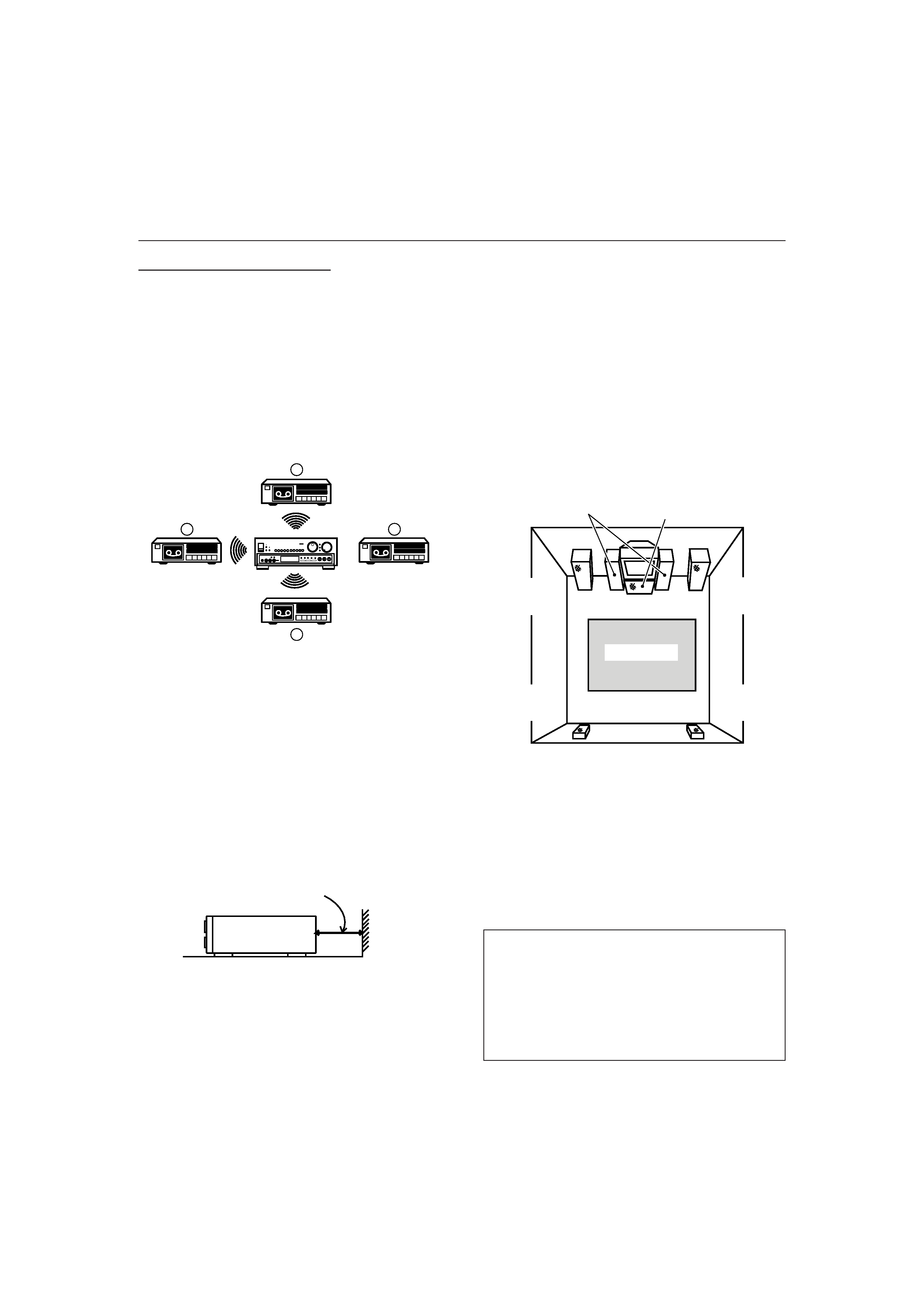
WALL OR CEILING MOUNTING
--
The appliance
should not be mounted to a wall or ceiling.
VENTILATION
-- The appliance should be situated so
that its location or position does not interfere with its
proper ventilation. For example, the appliance should
not be situated on a bed, sofa, rug, or similar surface
that may block the ventilation openings; or, placed in
a built-in installation, such as a bookcase or cabinet
that may impede the flow of air through the
ventilation openings.
HEAT
-- The appliance should be situated away from
heat sources such as radiators, heat registers, stoves,
or other appliances (including amplifiers) that produce
heat.
POWER SOURCES
-- The appliance should be
connected to a power supply only of the type
described in the operating instructions or as marked
on the appliance.
POWER-CORD PROTECTION
-- Power-supply cords
should be routed so that they are not likely to be
walked on or pinched by items placed upon or
against them. Pay particular attention to cords at
plugs, convenience receptacles, and the point where
they exit from the appliance.
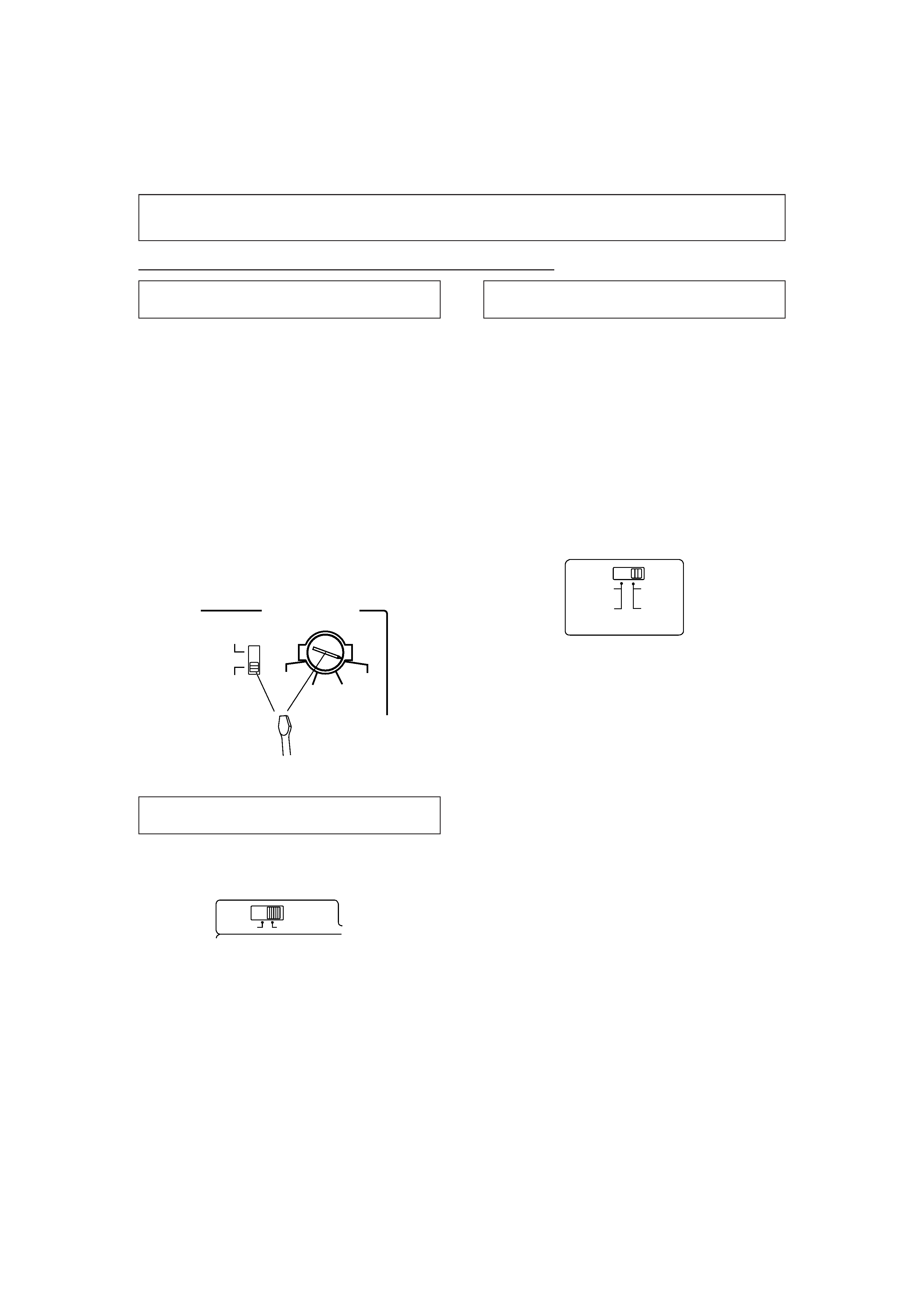
POLARIZATION
--
If your purchased product
is
provided with a polarized power plug, please read the
following instructions. This product is equipped with
a polarized alternating current line plug (a plug having
one blade wider than the other). This plug will fit into
the power outlet only one way. This is a safety
feature. If you are unable to insert the plug fully into
the outlet, try reversing the plug. If the plug should
still fail to fit, contact your electrician to replace your
obsolete outlet. Do not defeat the safety purpose of
the polarized plug.
CLEANING
-- The appliance should be cleaned only
with a polishing cloth or a soft dry cloth. Never clean
with furniture wax, benzine, insecticides or other
volatile liquids since they may corrode the cabinet.
POWER LINES
--
An outdoor antenna should be
located away from power lines.
NONUSE PERIODS
-- The power cord of the appliance
should be unplugged from the outlet when left
unused for a long period of time.
OBJECT AND LIQUID ENTRY
-- Care should be taken
so that objects do not fall and liquids are not spilled
into the enclosure through openings.
DAMAGE REQUIRING SERVICE
-- The appliance
should be serviced by a Pioneer authorized service
center or qualified service personnel when:
The
power­supply cord or the plug has been
damaged.
· Objects have fallen, or liquid has been spilled into the
appliance.
· The appliance has been exposed to rain.
· The appliance does not appear to operate normally or
exhibits a marked change in performance.
· The appliance has been dropped or the enclosure
damaged.
SERVICING
-- The user should not attempt to service
the appliance beyond that described in the operating
instructions. All other servicing should be referred to
qualified service personnel.
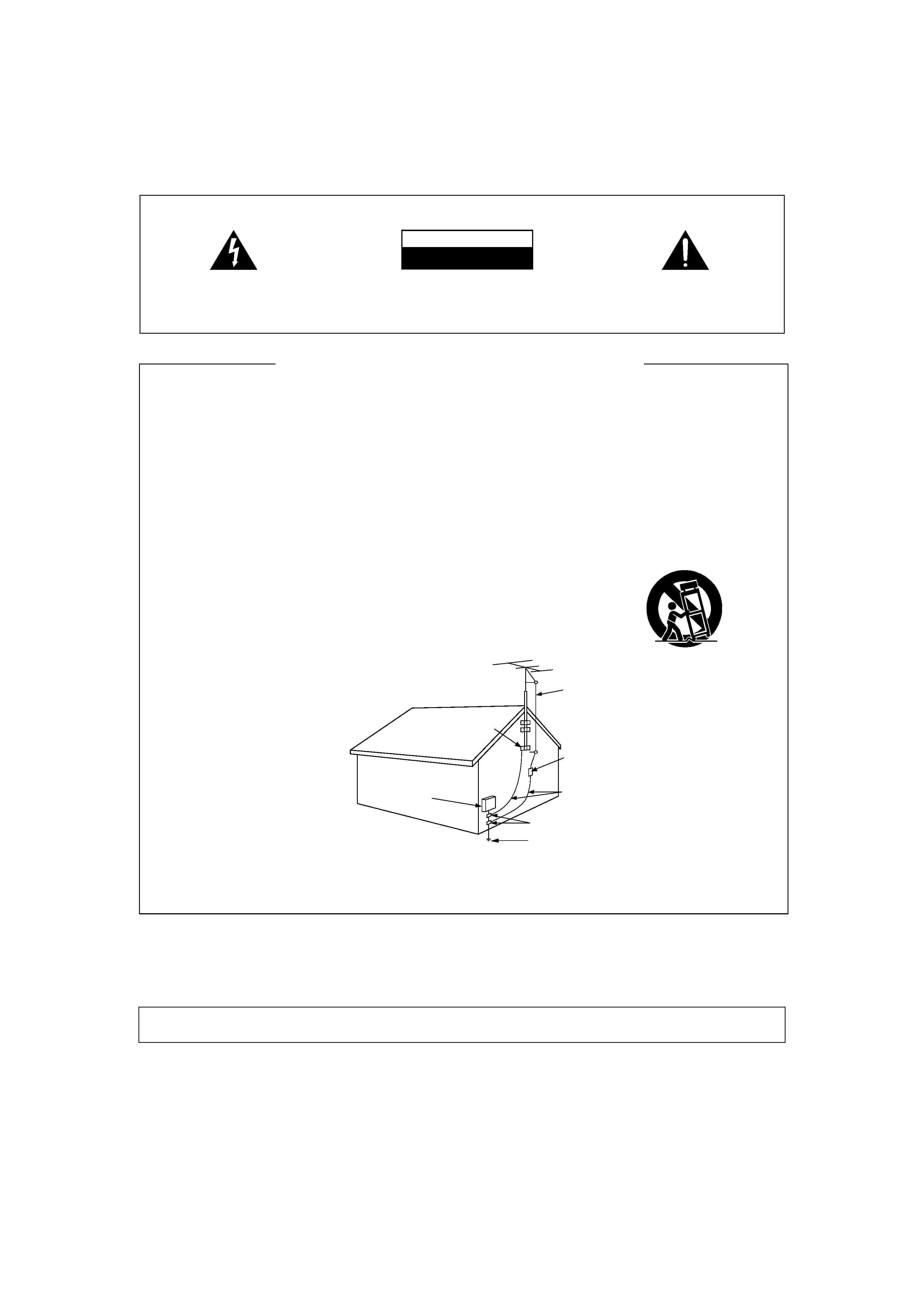
OUTDOOR ANTENNA GROUNDING
-- If an outside
antenna is connected to the antenna terminal, be
sure the antenna system is grounded so as to
provide some protection against voltage surges and
built-up static charges.
In the U.S.A. section 810 of the National Electrical
Code, ANSI/NFPA 70, provides information with
respect to proper grounding of the mast and
supporting structure, grounding of the lead-in wire to
an antenna discharge unit, size of grounding
conductors, location of antenna discharge unit,
connection
to
grounding
electrodes,
and
requirements for the grounding electrode. See Fig. A.
CART
-- An appliance and cart combination should be
moved with care. Quick stops, excessive force, and
uneven surfaces may cause the appliance and cart
combination to overturn.
NEC -- NATIONAL ELECTRIC CODE
GROUND
CLAMP
SAFETY INSTRUCTIONS
GROUND
CLAMP
GROUND
CLAMP
GROUND
CLAMP
GROUND
CLAMP
·
GROUND
CLAMP
GROUND
CLAMP
ANTENNA
LEAD-IN
WIRE
ANTENNA
DISCHARGE UNIT
(NEC SECTION 810
­ 20)
GROUNDING CONDUCTORS
(NEC SECTION 810
­ 21)
GROUND CLAMPS
POWER SERVICE GROUNDING
ELECTRODE SYSTEM
(NEC ART 250, PART H)
GROUND
CLAMP
ELECTRIC
SERVICE
EQUIPMENT
FIG. A
GROUND
CLAMP
GROUND
CLAMP
GROUND
CLAMP
Note to CATV system installer
This reminder is provided to call the CATV system installer's attention to Article 820-40 of the NEC that provides guidelines for proper
grounding and, in particular, specifies that the cable ground shall be connected to the grounding system of the building, as close to the
point of cable entry as practical.
Information to User
Alteration or modifications carried out without appropriate authorization may invalidate the user's right to operate the equipment.
background image
<ARB7050>
3
INSPECTION CHECKLIST
The Pioneer Receiver is packaged with the following
items:
If any of these items were not included in the package, contact
the dealer where you purchased the product from to obtain the
missing items or a complete replacement.
CONTENTS
BEFORE OPERATING
INSPECTION CHECKLIST ............................................................ 3
INSTALLATION ............................................................................ 4
SETTING THE SWITCHES
FOR THE MULTI-VOLTAGE MODEL ONLY ...................... 4
INSTALLATION PRECAUTIONS ............................................. 5
CONNECTIONS
ANTENNA CONNECTIONS .................................................... 6
AUDIO SYSTEM CONNECTIONS .......................................... 7
VIDEO SYSTEM CONNECTIONS ........................................... 8
SPEAKER SYSTEM CONNECTIONS ...................................... 9
IR REPEATER CONNECTION ................................................ 10
PANEL FACILITIES
REAR PANEL FACILITES ............................................................ 11
FRONT PANEL FACILITIES ........................................................ 13
DISPLAY SECTION ............................................................... 15
OPERATIONS
OPERATING THE TUNER .......................................................... 16
TUNING INTO STATIONS .................................................... 16
FREQUENCY PRESETTING .................................................. 16
LISTENING TO BROADCASTS USING PRESET TUNING ... 16
RECEIVING FM SIMULCAST TV PROGRAMS ..................... 17
OPERATING THE AUDIO/VIDEO COMPONENTS ..................... 17
PLAYBACK ............................................................................ 17
RECORDING WITH A CASSETTE DECK .................................... 18
RECORDING WITH TAPE 1 ................................................... 18
RECORDING WITH TAPE 2 ................................................... 18
USING VCR 1, VCR 2 FOR AUDIO RECORDING .................. 18
COPYING TAPES .................................................................. 18
VIDEO RECORDING ................................................................... 19
SURROUND EFFECT .................................................................. 19
REMOTE CONTROL OPERATION
PUTTING BATTERIES INTO THE REMOTE CONTROL UNIT ... 20
REMOTE CONTROL RANGE ................................................ 20
RECEIVER CONTROL BUTTONS .......................................... 21
OPERATING OTHER COMPONENTS ................................... 21
OPERATING USING GUI
RECEIVER CONTROL BUTTONS .......................................... 24
OPERATING THE TUNER .......................................................... 25
MANUAL/AUTO TUNING ..................................................... 25
PRESET TUNING .................................................................. 25
OPERATING OTHER COMPONENTS ........................................ 26
COPY OPERATION ..................................................................... 28
USING THE VIDEO SIGNAL SELECTOR ................................... 28
SOUND EDIT OPERATION ........................................................ 29
SETTING THE SPEAKER MODE ........................................... 29
LEVEL AND BALANCE ADJUSTMENT ................................ 30
REMOTE SET UP ........................................................................ 31
ONE TOUCH OPERATION SET UP ............................................ 33
TROUBLESHOOTING ................................................................ 34
APPENDICES
APPENDIX A: SPECIFICATIONS ................................................ 36
APPENDIX B: SURROUND EFFECT .......................................... 37
APPENDIX C: DOLBY AC-3 SURROUND .................................. 38
Operating Instructions
Main-Repeater
AM Loop Antenna
FM T-type antenna
Remote control unit
Dry cell batteries
(size "AA" IEC R6P) x 2
Mini-Repeater
Warranty Card
(Not supplied in multi-voltage model.)
background image
<ARB7050>
4
INSTALLATION
SETTING THE SWITCHES FOR THE MULTI-VOLTAGE MODEL ONLY
TWO VOLTAGE SELECTOR SWITCHES
(Not available on U.S. and Canadian models)
Only multi-voltage models are provided with these
switches. U.S. and Canadian models are not provided
with these switches. Mains voltages in Saudi Arabia are
127 V and 220 V only. Never use this model with the 110
V setting in Saudi Arabia.
The line voltage selector switches are on the rear panel. Before
your model is shipped from the factory, these switches are set
to the power requirements of the destination. Check that they
are set properly before plugging the power cord into the
household wall socket. If the voltage is not properly set or if you
move to an area where the voltage requirements differ, adjust
the selector switches as follows.
1. Use a medium-size screwdriver.
2. First, insert the screwdriver in the groove of the voltage
selector at the right, and adjust so that the tip of the groove
points to the voltage value of your area.
3. Next, insert the screwdriver in the groove of the voltage
selector at the left and adjust until the voltage is the same as
at the right.
PAL/NTSC SWITCH
(Not available on U.S. and Canadian models)
This unit uses the TV screen to operate the system. Set the rear
panel PAL/NTSC switch to match your TV's color system. The
screen will be unclear if the color system does not match.
CHANNEL STEP/FM DE-EMPHASIS SWITCH
(Not available on U.S. and Canadian models)
The unit has been factory preset to the channel allocation and
de-emphasis value for the area in which it is to be sold. If these
values are set incorrectly, the tuned in frequency may be wrong,
or sound may be distorted, resulting in an inability to reproduce
reception signals at their proper sound quality. For this reason,
be sure to confirm that the values are set correctly before first
using the unit.
(FM 100 kHz/75
µs, AM 10 kHz) position:
Set to this position for areas with an FM reception step of 100
kHz, de-emphasis 75
µs and AM 10 kHz.
(FM 50 kHz/50
µs, AM 9 kHz) position:
Set to this position, for areas with an FM reception step of 50
kHz, de-emphasis 50
µs and AM 9 kHz.
NOTE:
When unsure about the channel allocation and de-emphasis
values for your area, consult your dealer for correct information.
Medium-size screwdriver
TWO VOLTAGE SELECTORS
110V
120
127V
220V
240V
220V
110V
120-127V
240V
PAL
NTSC
FM 50kHz
/50
S
AM 9kHz
CHANNEL
/FM DE-
100kHz
/75
S
10kHz
STEP
EMPHASIS
background image
<ARB7050>
5
INSTALLATION
INSTALLATION PRECAUTIONS
INSTALLING THE RECEIVER
÷ Place the unit on a stable platform next to the television and
stereo system to be used with the unit.
÷ When using the unit with a stereo system, your speakers
should be placed away from your television (or TV monitor).
÷ Do not place heavy objects such as a television or TV monitor
on top of the unit.
÷ Do not place the unit on top of your TV set or TV monitor. Also,
keep the unit away from devices such as cassette decks which
are sensitive to magnetic fields.
If the cassette deck is installed in the A positions as shown in
the drawing below, it may be adversely affected during
playback. If possible, it is better to install it in the B position.
POWER-CORD CAUTION
Handle the power cord by the plug. Do not pull out the plug by
tugging the cord and never touch the power cord when your
hands are wet as this could cause a short circuit or electric
shock. Do not place the unit, a piece of furniture, etc., on the
power cord, or pinch the cord. Never make a knot in the cord or
tie it with other cords. The power cords should be routed such
that they are not likely to be stepped on. A damaged power cord
can cause a fire or give you an electrical shock. Check the power
cord once in a while. When you find it damaged, ask your
nearest PIONEER authorized service center or your dealer for a
replacement.
SURROUND SPEAKER INSTALLATION EXAMPLE
To get the best effect out of the surround system, place the
speakers as shown below.
An example for center speaker location
INSTALL THE RECEIVER IN A WELL-VENTILATED
PLACE AWAY FROM HEAT AND HUMIDITY
Do not install the unit in a location subject to direct sunlight, or
near a stove or radiator, etc. This could adversely affect the
cabinet and internal components. Also, avoid installing the unit
in a humid or dusty location. This could result in a malfunction
or accident. Do not install near a cooking stove where the unit
could be affected by smoke, steam, or heat. Avoid placing the
unit on surfaces such as shaggy carpets, beds and sofas which
may block ventilation under the unit and may cause damage.
÷ The rear panel vents are designed to disperse heat from the
unit. Be careful that curtains or other items do not block the
vents.
÷ To improve heat dispersion, set the unit so that it is at least
20 cm (8 inches) away from the wall.
At least 20 cm (8 inches)
When using a single
center speaker
When using dual center
speakers
NOTE:
÷ To avoid interference with the picture on a nearby TV set, use
magnetically shielded speaker systems. This is particularly
important for the center speaker since it is usually located
closest to the TV.
÷ Position the left and right channel speakers at equal distances
from the TV set and approximately 1.8 m (6 feet) from each
other.
÷ Position the center speaker above, below, or behind the TV set.
Sound may not appear to coincide with the picture if you
position it next to the TV set.
÷ Rear speakers are best positioned slightly above ear level.
You can set this unit to match the requirements and
specifications of your stereo system's speakers (whether or
not center speaker(s), rear speakers or a sub-woofer are
used, speaker size, etc.) to assure optimum sound quality.
Before using, perform settings in the SPEAKER MODE (refer
to page 29).
NOTE:
This unit does not feature conventional switching between
NORMAL / WIDE / PHANTOM center modes.
TV
CENTER SPEAKER
FRONT
REAR
RIGHT
FRONT
SPEAKER
RIGHT
SURROUND
SPEAKER
LEFT
FRONT
SPEAKER
LEFT
SURROUND
SPEAKER
Listening Area
A
A
A
B
Receiver

Reviews

There are no reviews of this manual yet.