PIONEER CORPORATION 4-1, Meguro 1-chome, Meguro-ku, Tokyo 153-8654, Japan
PIONEER ELECTRONICS (USA) INC. P.O. Box 1760, Long Beach, CA 90801-1760, U.S.A.
PIONEER EUROPE NV Haven 1087, Keetberglaan 1, 9120 Melsele, Belgium
PIONEER ELECTRONICS ASIACENTRE PTE. LTD. 253 Alexandra Road, #04-01, Singapore 159936
PIONEER CORPORATION 2004
c
ORDER NO.
TS-WX206A
TRT1134
H IZX FEB. 2004 Printed in Japan
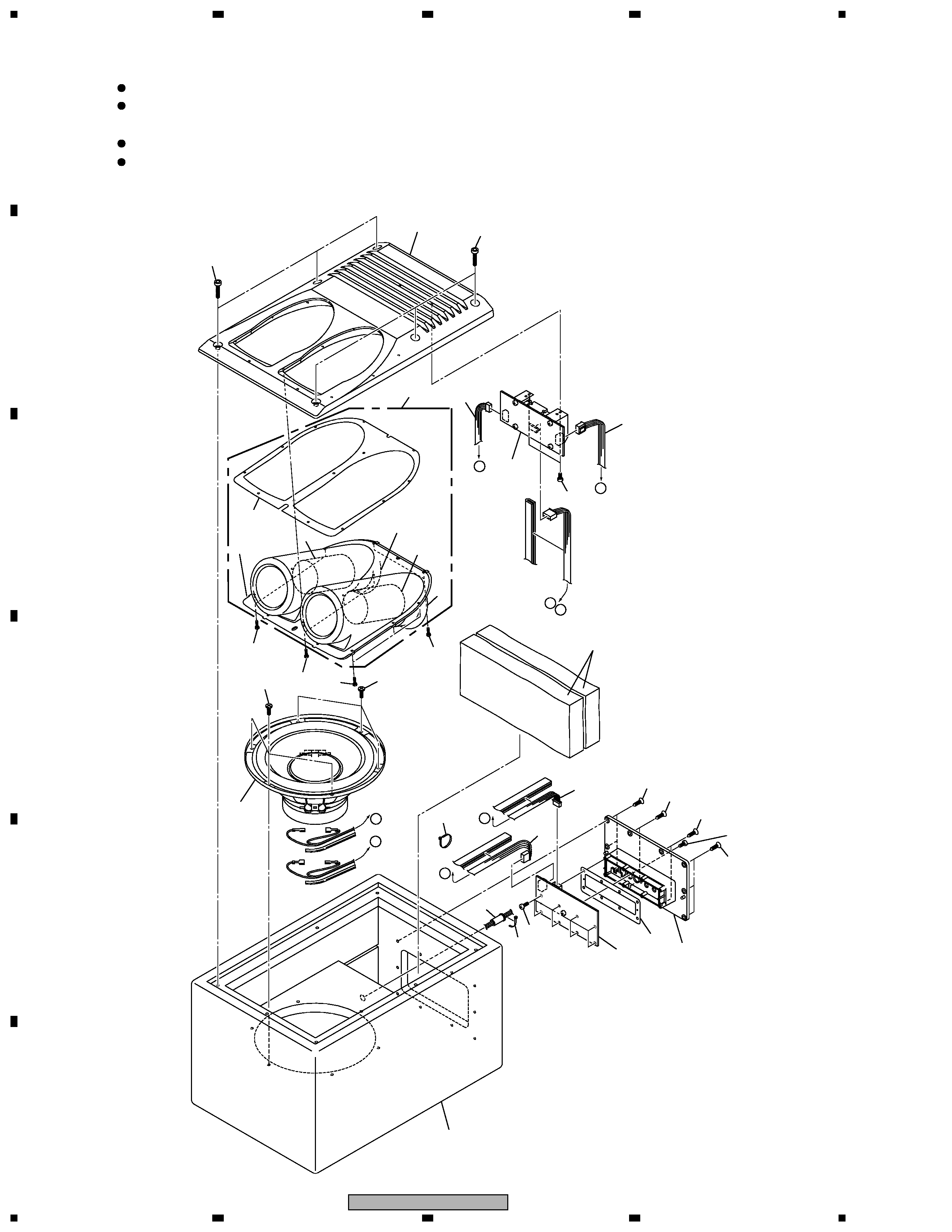
AMPLIFIED BANDPASS SUBWOOFER
XCN/EW
1. SPECIFICATIONS
· Speaker specifications
Size .................................................................
200mm (8"Dia.)
High compliance, rolled edge
Heat-resistant voice coil
Strontium magnet : 650g (23oz)
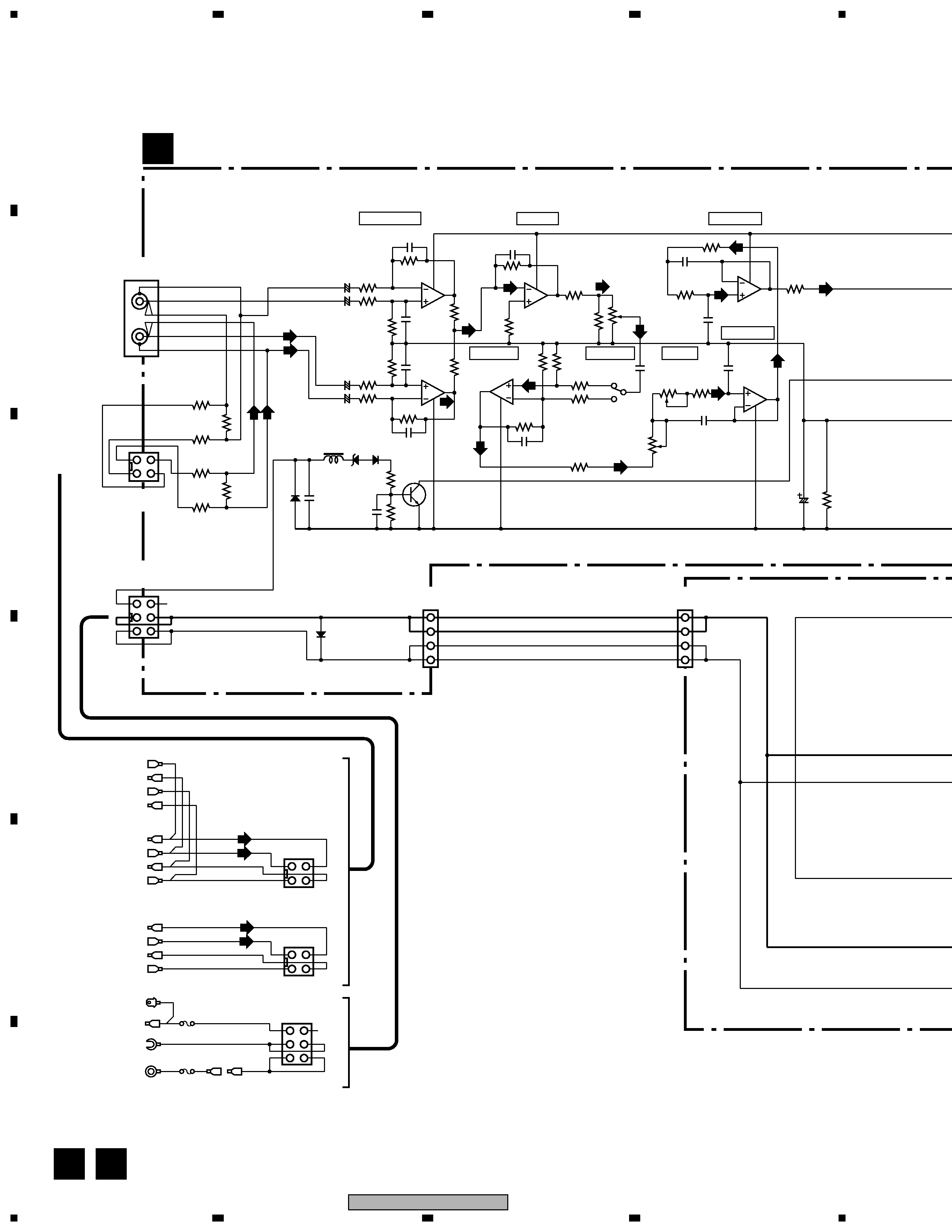
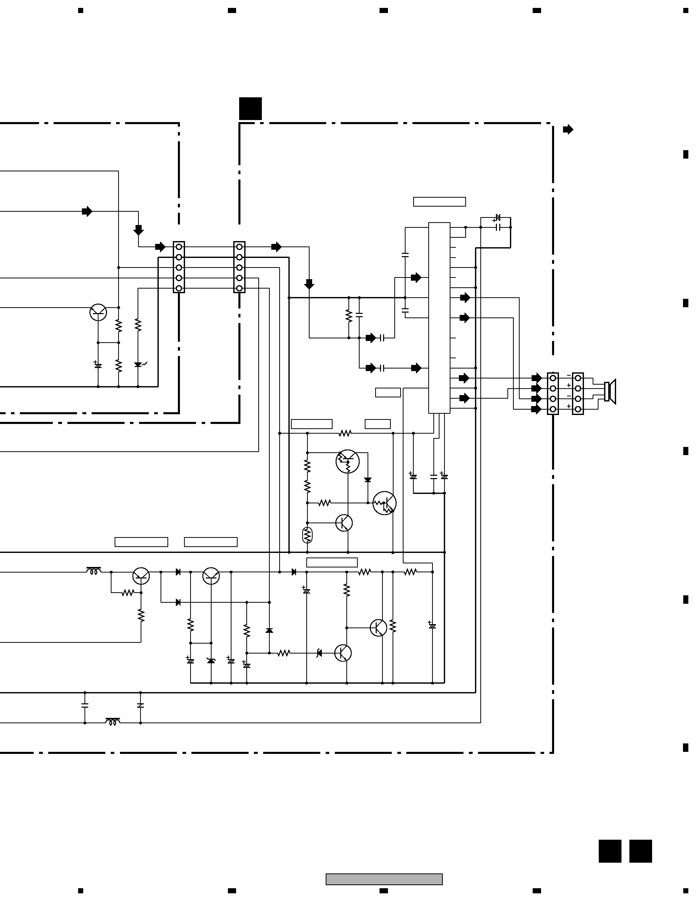
· Amplifier
Max. Power output ................................................. 150W (80Hz)
DIN output power (DIN45324, 65Hz, 2
+B=14.4V) ......... 70W
INPUT LEVEL (at Gain Max)
(RCA) .................................................. 100mV+100mV / 20k
(Speaker line) ........................................................ 2V+2V / 5k
Power source ......................... DC14.4V (10.8~15.6V allowable)
Max. current consumption ..................................................... 10A
Grounding .......................................................... Negative ground
· Speaker system ...................................................... Bandpass type
· Cabinet meterial ..................................................... Particle board
· Sesitivity ....................................... 107dB / W (In car, SUV type)
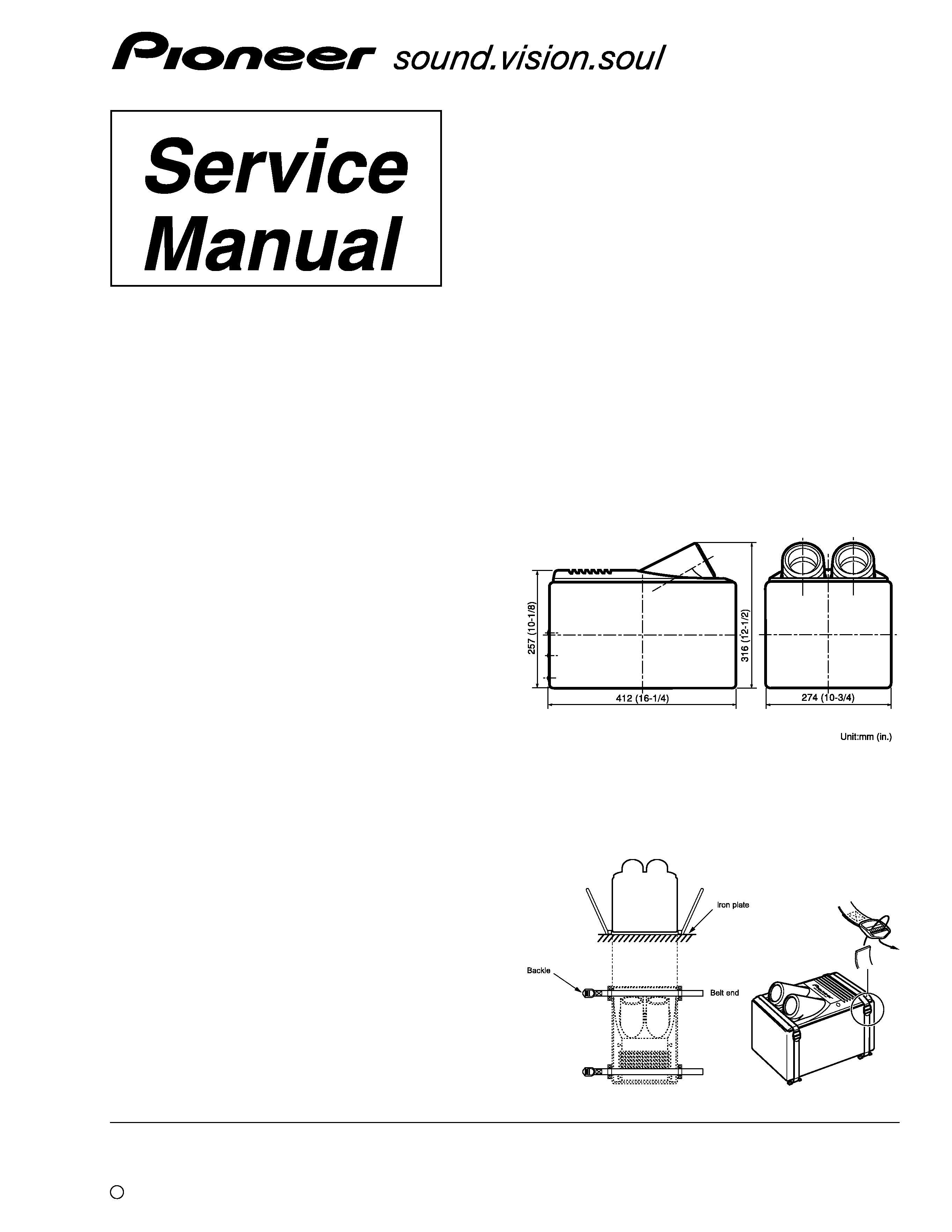
· Size .......... 412mm (16-1/4")(W)
×274mm (10-3/4")(D)×316mm (12-1/2")(H)
· Weight (including accessory parts) ................. 9.67kg (21lb 5oz)
· Gross weight (including packaging) ............. 11.3kg (24lb 14oz)
Note :
Specifications and the design are subject to possible
modification without notice due to improvements.
¶ Figure of Measurement
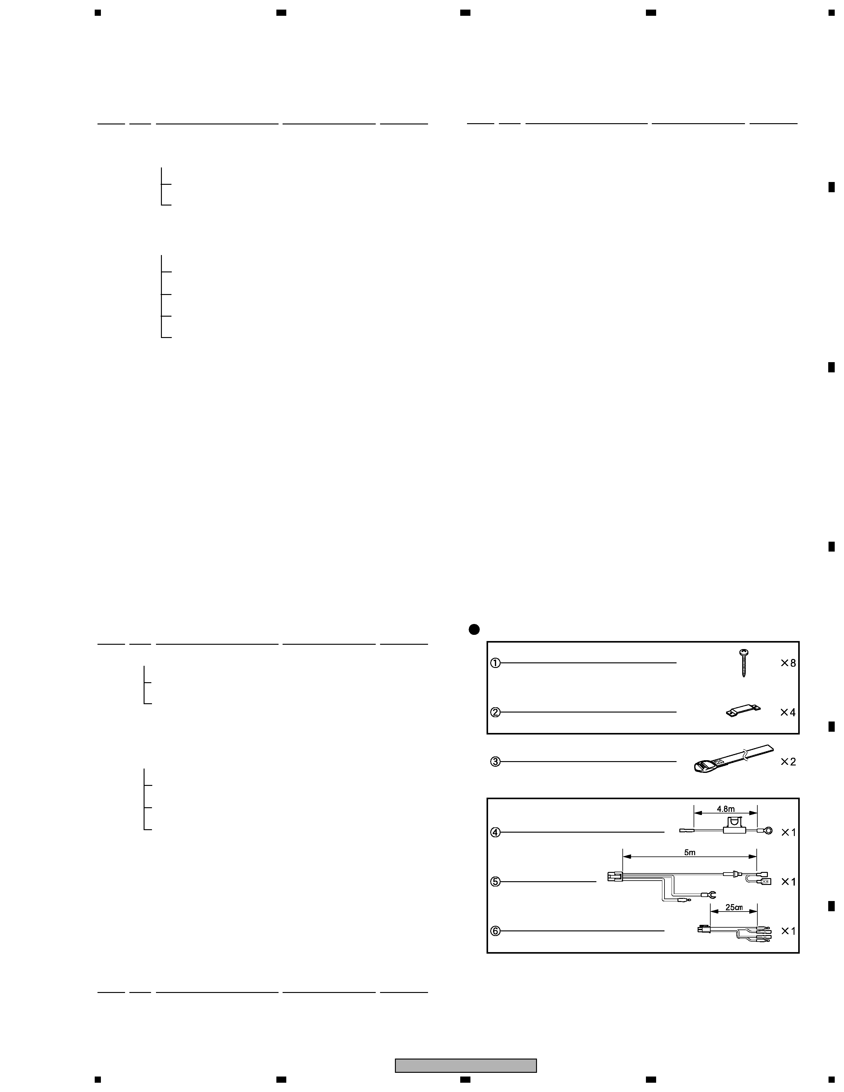
2. HOW TO INSTALL