
SX-LX70SW
4
12
34
1
234
C
D
F
A
B
E
CONTENTS
SAFETY INFORMATION ..................................................................................................................................... 2
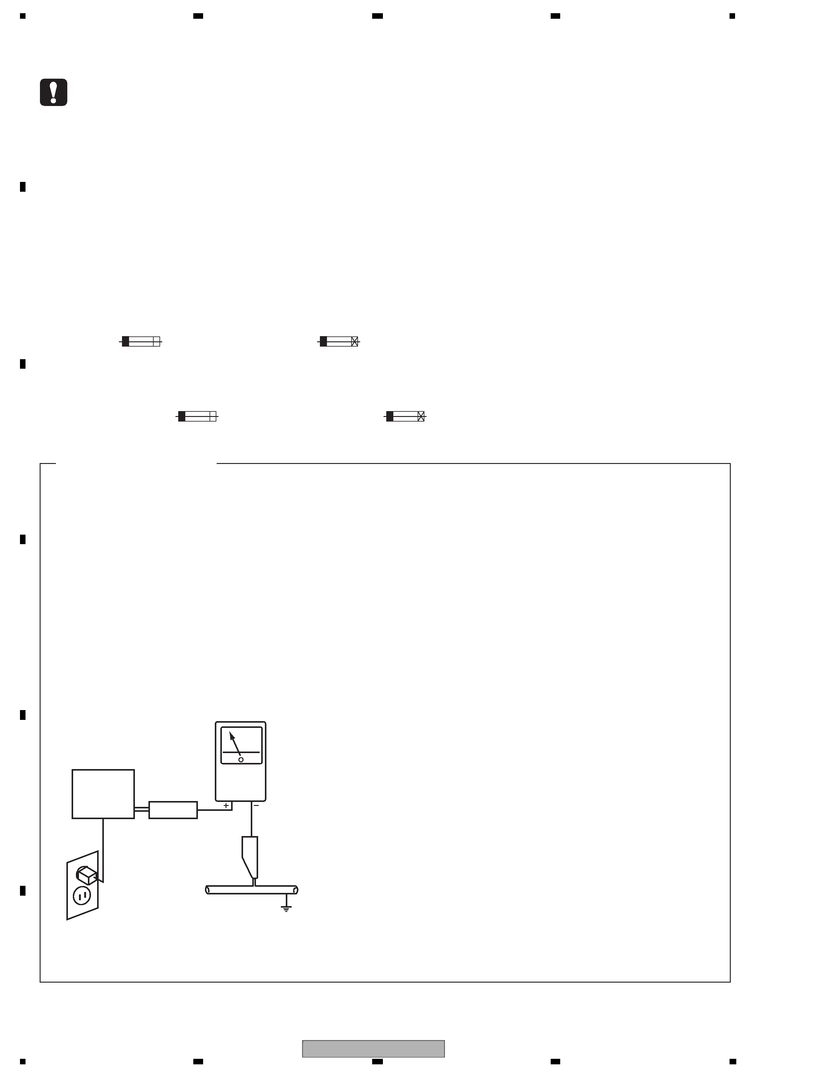
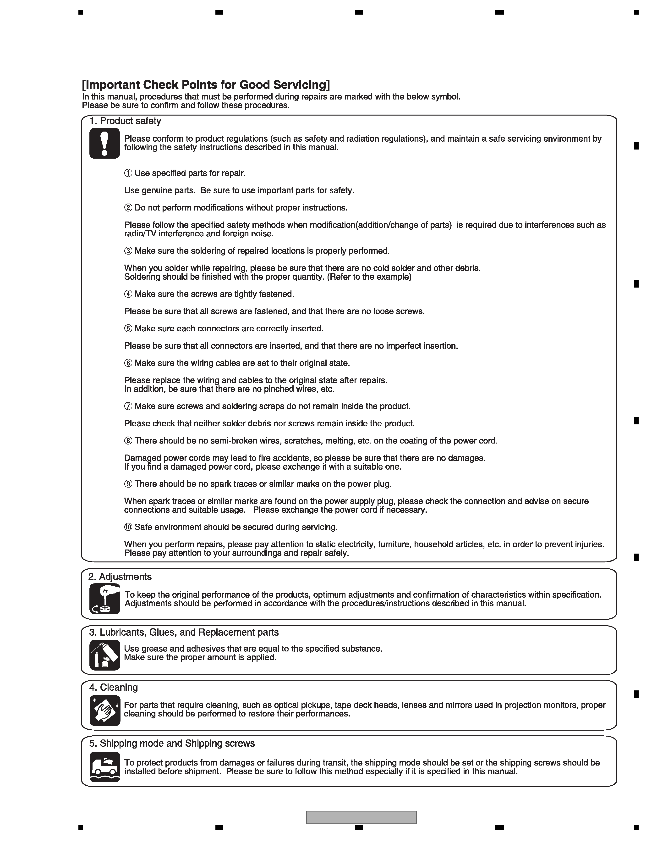
1. SERVICE PRECAUTIONS ............................................................................................................................... 5
2. SPECIFICATIONS ............................................................................................................................................ 6
2.1 ACCESSORIES ......................................................................................................................................... 6
2.2 SPECIFICATIONS...................................................................................................................................... 7
2.3 PANEL FACILITIES .................................................................................................................................... 8
3. BASIC ITEMS FOR SERVICE........................................................................................................................ 12
3.1 CHECK POINTS AFTER SERVICING..................................................................................................... 12
3.2 PCB LOCATIONS .................................................................................................................................... 13
3.3 JIGS LIST ................................................................................................................................................ 14
3.4 CLEANING............................................................................................................................................... 14
4. BLOCK DIAGRAM.......................................................................................................................................... 16
4.1 OVERALL WIRING CONNECTION DIAGRAM ....................................................................................... 16
4.2 OVERALL BLOCK DIAGRAM.................................................................................................................. 18
5. DIAGNOSIS.................................................................................................................................................... 20
5.1 HDMI TROUBLESHOOTING ................................................................................................................... 20
5.2 DSP TROUBLESHOOTING..................................................................................................................... 27
5.3 XM TROUBLESHOOTING....................................................................................................................... 42
5.4 SIRIUS TROUBLESHOOTING ................................................................................................................ 44
5.5 CIRCUIT DESCRIPTION OF DIGITAL AMP. SECTION .......................................................................... 45
5.6 SPECIFICATIONS FOR THE PROTECTION CIRCUITS FOR THE DIGITAL AMPLIFIER ..................... 46
5.7 CONDITIONS FOR SWITCHING THE ROTAIONS SPEED OF THE FAN.............................................. 47
5.8 ERROR LIST............................................................................................................................................ 48
6. SERVICE MODE ............................................................................................................................................ 52
6.1 TEST MODE ............................................................................................................................................ 52
6.2 SERVICE TEST MODE ........................................................................................................................... 54
7. DISASSEMBLY............................................................................................................................................... 57
8. EACH SETTING AND ADJUSTMENT ........................................................................................................... 62
8.1 ADJUSTMENT ......................................................................................................................................... 62
8.2 HOW TO UPDATE THE FLASH ROMS FOR VARIOUS MICROCOMPUTERS...................................... 62
8.3 HOW TO UPDATE THE DSP FLASH ROM BY PLAYING BACK A CD................................................... 64
9. EXPLODED VIEWS AND PARTS LIST.......................................................................................................... 66
9.1 PACKING (SX-LX70SW) .......................................................................................................................... 66
9.2 PACKING (AS-LX70)................................................................................................................................ 68
9.3 EXTERIOR SECTION.............................................................................................................................. 70
9.4 RECEIVER UNIT ..................................................................................................................................... 72
9.5 DISPLAY UNIT ......................................................................................................................................... 74
9.6 REMOTE CONTROL ............................................................................................................................... 76
10. SCHEMATIC DIAGRAM ............................................................................................................................... 78
10.1 MAIN ASSY (1/7) ................................................................................................................................... 78
10.2 MAIN ASSY (2/7) ................................................................................................................................... 80
10.3 MAIN ASSY (3/7) ................................................................................................................................... 82
10.4 MAIN ASSY (4/7) ................................................................................................................................... 84
10.5 MAIN ASSY (5/7) ................................................................................................................................... 86
10.6 MAIN ASSY (6/7) ................................................................................................................................... 88
10.7 MAIN ASSY (7/7) ................................................................................................................................... 90
10.8 AMP ASSY (1/2) .................................................................................................................................... 92
10.9 AMP ASSY (2/2) .................................................................................................................................... 94
10.10 CONNECTION and EARTH ASSYS .................................................................................................... 96
10.11 HDMI ASSY (1/2) ................................................................................................................................. 98
10.12 HDMI ASSY (2/2) ............................................................................................................................... 100
10.13 AINB ASSY ........................................................................................................................................ 102
10.14 FL, REMOCON and BTOB ASSYS ................................................................................................... 104
10.15 POWER SUPPLY UNIT...................................................................................................................... 106
11. PCB CONNECTION DIAGRAM ................................................................................................................. 109
11.1 MAIN ASSY ......................................................................................................................................... 110
11.2 AMP ASSY........................................................................................................................................... 114
11.3 CONNECTION ASSY .......................................................................................................................... 118
11.4 EARTH ASSYS .................................................................................................................................... 119
11.5 HDMI ASSY ......................................................................................................................................... 120
11.6 BTOB ASSY ......................................................................................................................................... 124
11.7 AINB ASSY .......................................................................................................................................... 125
11.8 FL ASSY .............................................................................................................................................. 127
11.9 POWER SUPPLY UNIT........................................................................................................................ 129
12. PCB PARTS LIST ....................................................................................................................................... 131


 I Service Manual")


