2
1
23
4
12
3
4
C
D
F
A
B
E
S-X360
NSP
1
CS Assy (Front)
SMW1927
NSP
2
CS Assy (Surround)
SMW1928
NSP
3
CS Assy (Center)
SMW1929
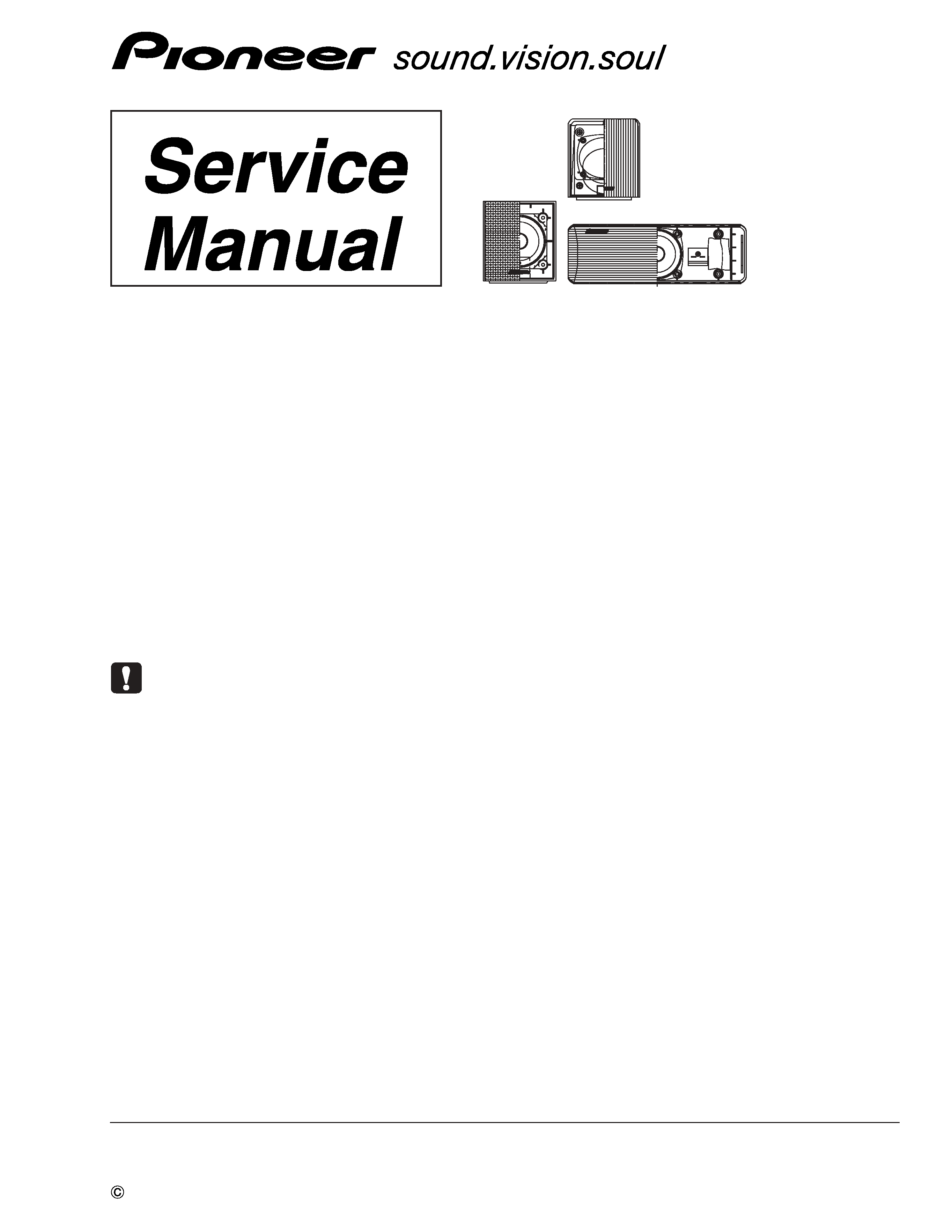
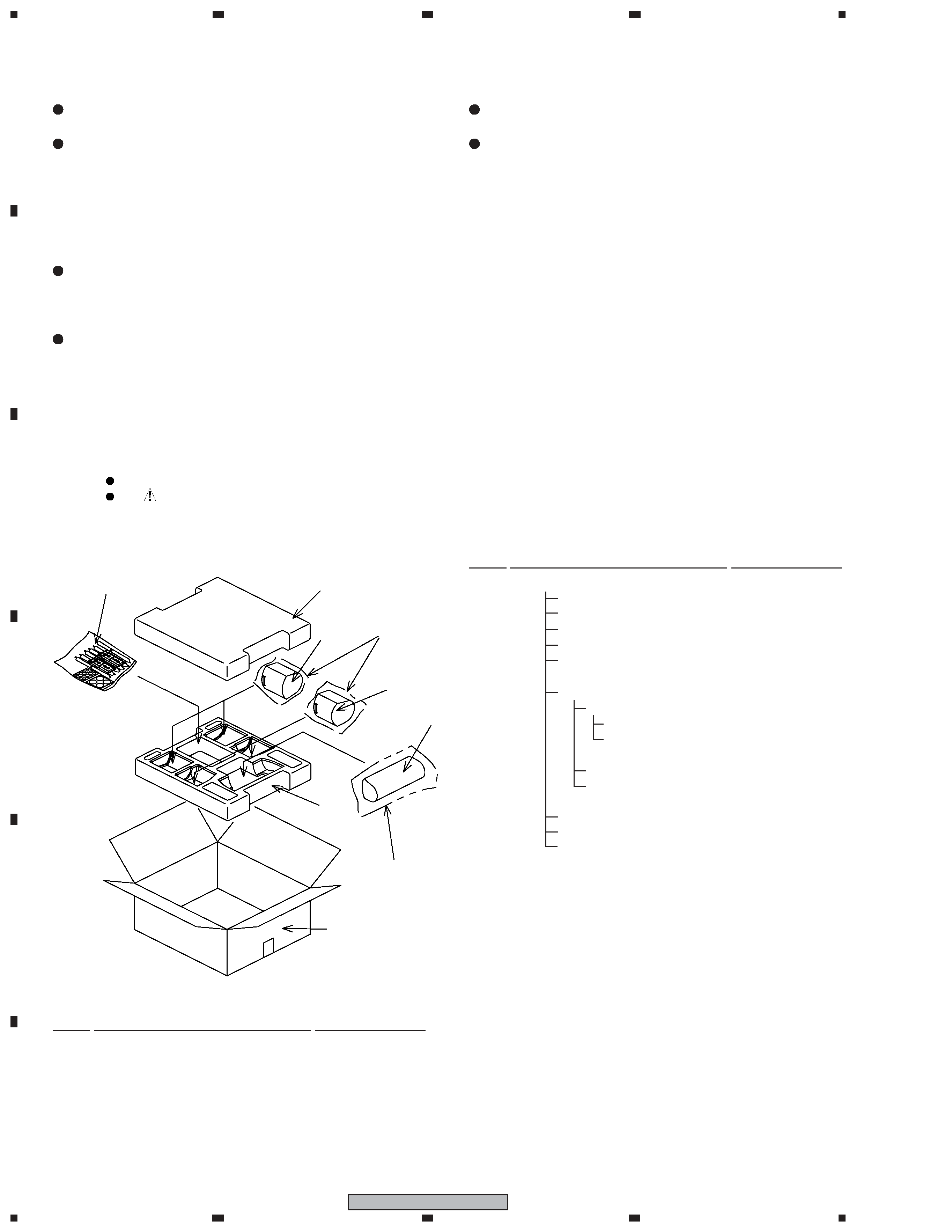
2-1. PACKING
Parts marked by "NSP" are generally unavailable because they are not in our Master Spare Parts List.
The
mark found on some component parts indicates the importance of the safety factor of the part.
Therefore, when replacing, be sure to use parts of identical designation.
NOTES:
2. PARTS LIST
Mark No.
Description
Part No.
1
2
3
6
7
5
5
8
4
Mark No.
Description
Part No.
NSP
4
Accessory Set
SEA1711
Speaker Wire (FL: White)
SDS1174
Speaker Wire (FR: Red)
SDS1175
Speaker Wire (SL: Blue)
SDS1176
Speaker Wire (SR: Gray)
SDS1177
Speaker Wire (C: Green)
SDS1178
NSP
Bracket Set
SEA1680
NSP
Screw Set
SEA1676
Screw
BMZ50P120FNC
Polyethylene Bag S0
SHL1314
Mounting Bracket
SNN1047
Polyethylene Bag S1
SHL1429
Non Skid Pad (for Subwoofer) SEC1912
Non Skid Pad (for Front, Center)SEP6002
Polyethylene Bag S2
SHL1251
5
Protector
SHA2509
6
Polyethylene Bag S1
SHL1419
7
Polyethylene Bag S2
SHL1420
for XTW/UC type
NSP
Model Label (FL)
SAN3794
NSP
Model Label (FR)
SAN3795
NSP
Model Label (SL)
SAN3796
NSP
Model Label (SR)
SAN3797
NSP
Model Label (C)
SAN3798
8
Packing Case
SHG2722
for XTW/EW5 type
NSP
Model Label (FL)
SAN3820
NSP
Model Label (FR)
SAN3821
NSP
Model Label (SL)
SAN3822
NSP
Model Label (SR)
SAN3823
NSP
Model Label (C)
SAN3824
8
Packing Case
SHG2723
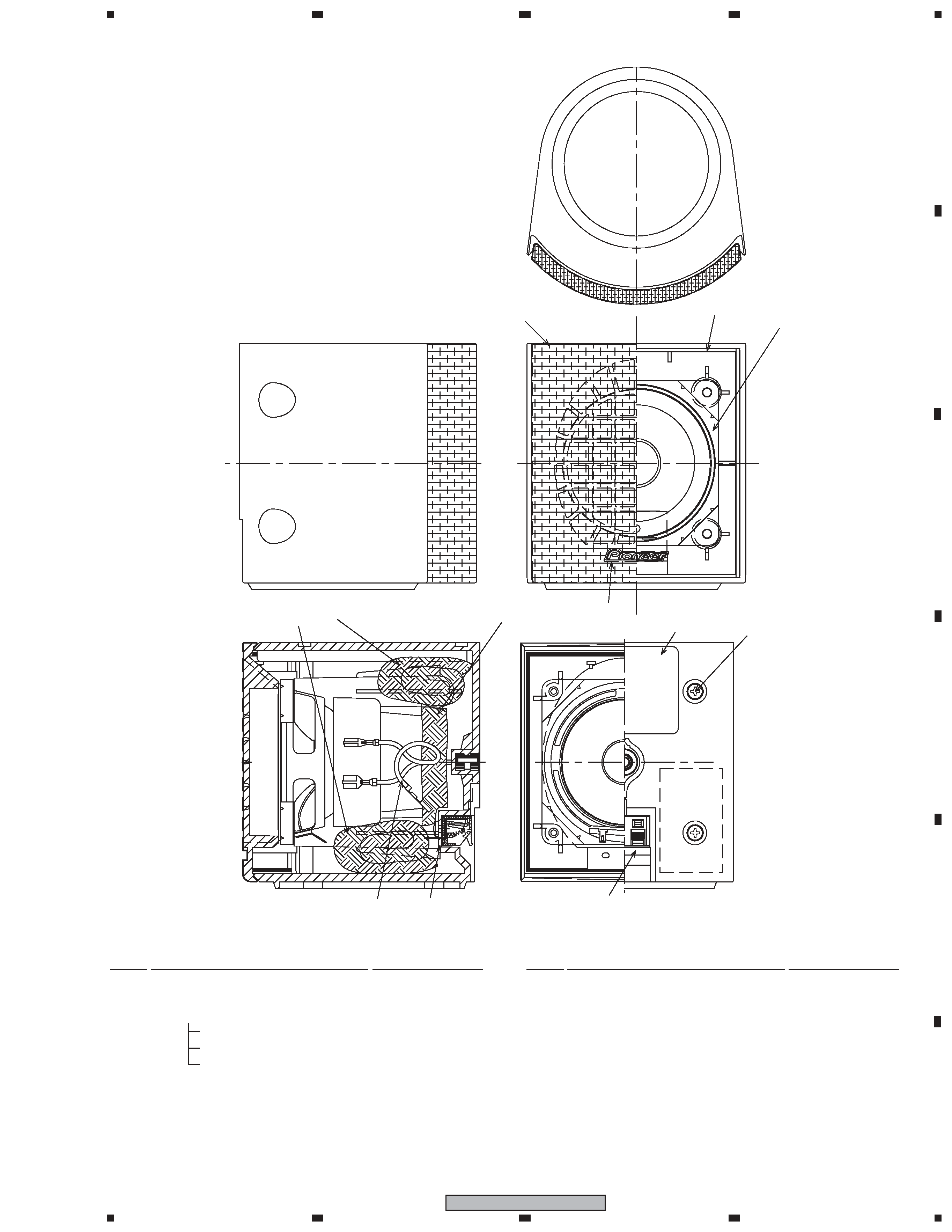
1. FOR PRECAUTION OF REASSEMBLY AND DISASSEMBLY
CS Assy ( Front )
The grille assy is attached to the cabinet by 4 external screws.
To detach it, unfasten those screws.
The speaker unit, together with the grille assy, is attached to the
cabinet by 4 external screws.
To detach it, first unfasten those screws. Next remove the cabi-
net. Then remove the cable.
When attaching it, face its terminal downward.
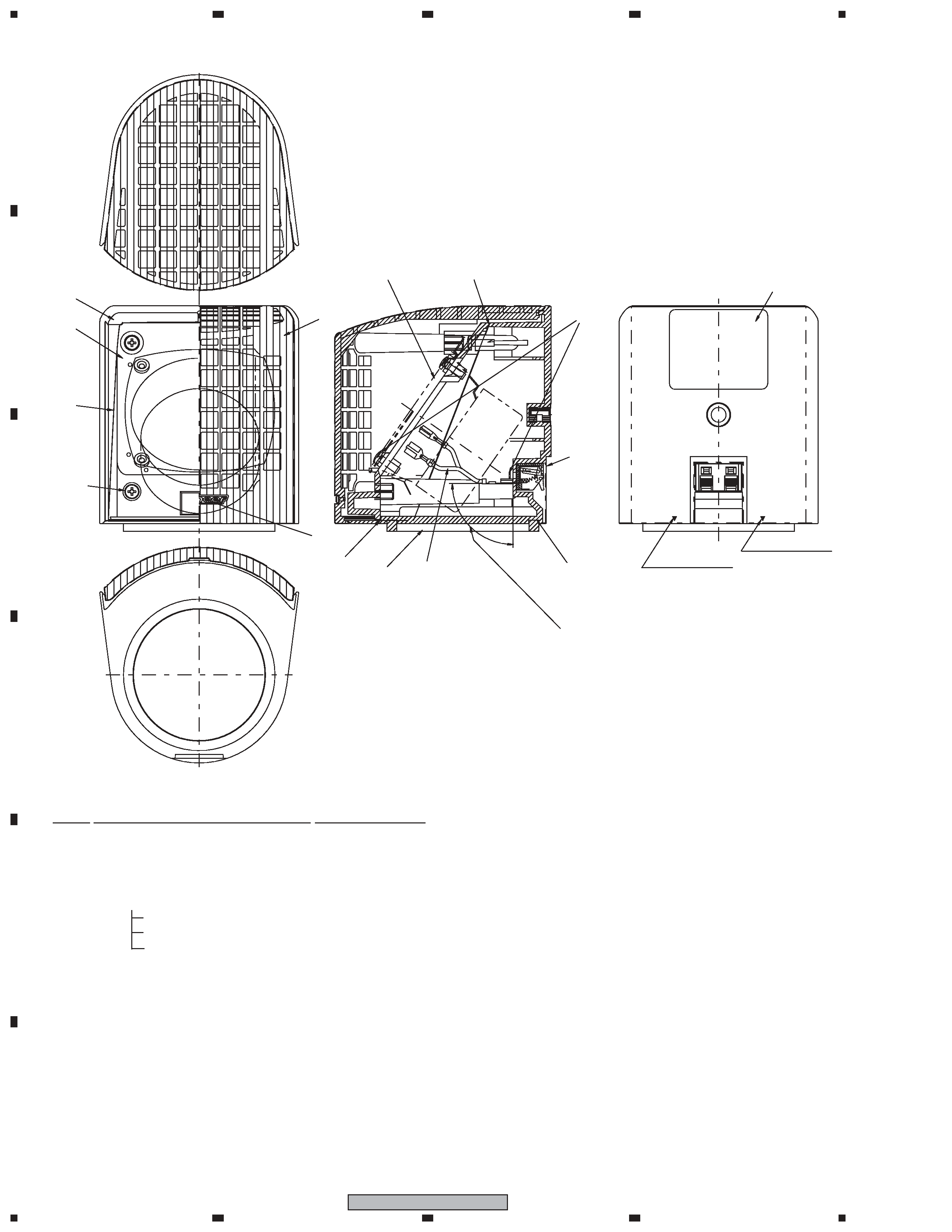
CS Assy ( Surround )
The grille assy is attached to the cabinet by its bosses. To de-
tach it, pry it open by inserting a flat blade screw driver into
lower slot.
To attach it, press it to the inner baffle.
The speaker unit is attached to the inner baffle by 4 external
screws.
To detach it, first remove the grille assy. Next unfasten those
screws, and remove the cable.
When attaching it, face its terminal downward.
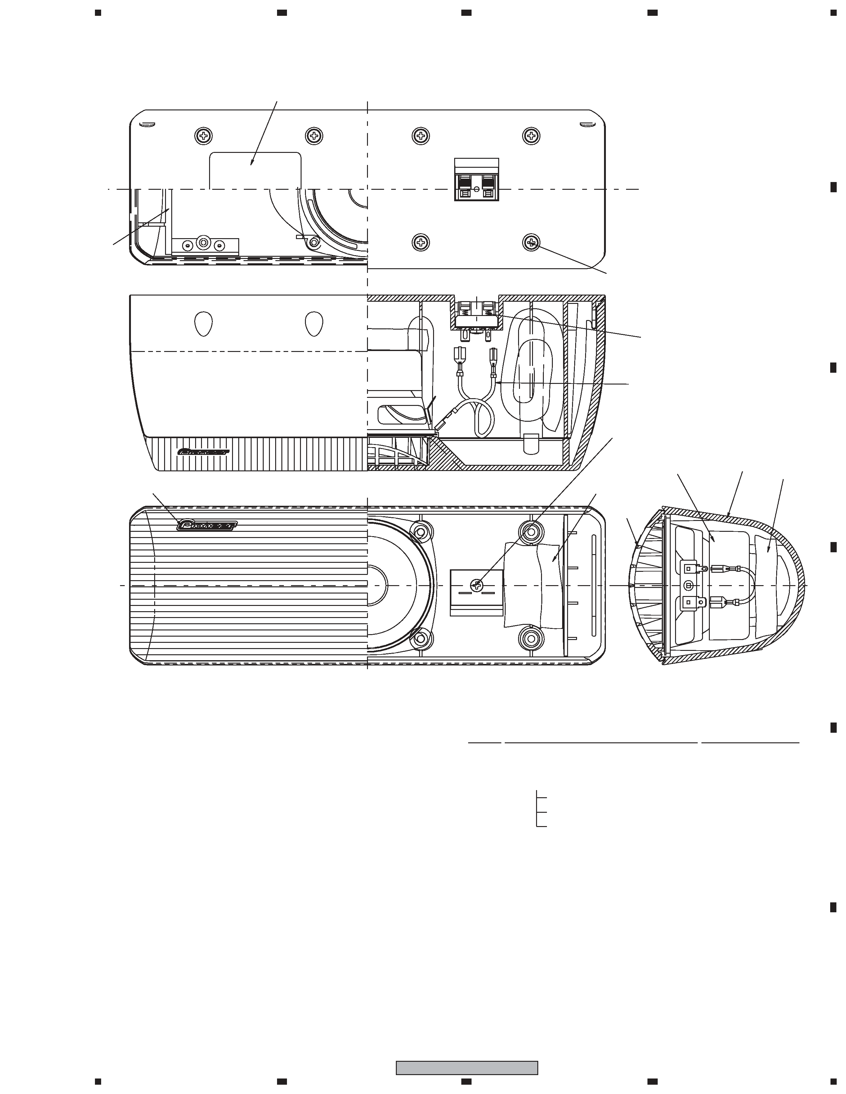
CS Assy ( Center )
The grille assy is attached to the cabinet by 8 external screws.
To detach it ,unfasten those screws.
The speaker unit, together with the grille assy, is attached to the
cabinet by 4 external screws.
To detach it, first remove the grille assy. Next remove the cabi-
net. Then remove the cable.
When attaching it, face its terminal toward the input terminal.
Packing Parts List