ORDER NO.
PIONEER CORPORATION 4-1, Meguro 1-chome, Meguro-ku, Tokyo 153-8654, Japan
PIONEER ELECTRONICS SERVICE, INC. P.O. Box 1760, Long Beach, CA 90801-1760, U.S.A.
PIONEER EUROPE NV Haven 1087, Keetberglaan 1, 9120 Melsele, Belgium
PIONEER ELECTRONICS ASIACENTRE PTE. LTD. 253 Alexandra Road, #04-01, Singapore 159936
PIONEER CORPORATION 2001
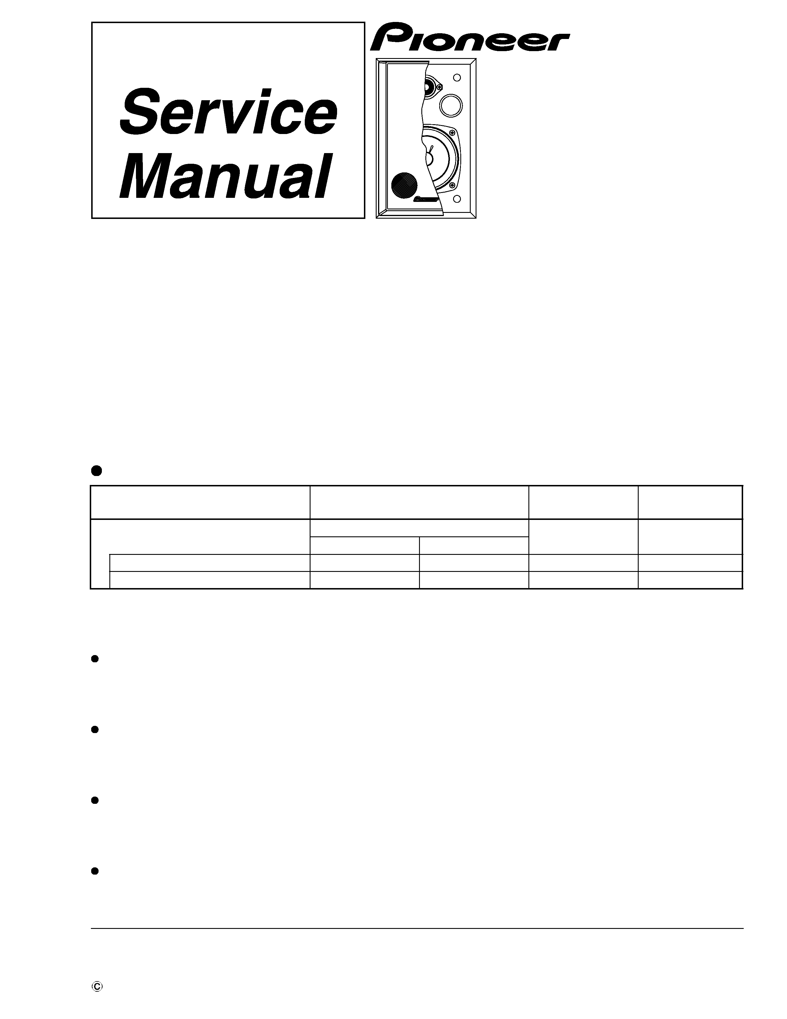
SPEAKER SYSTEM
RRV2437
TZZK FEB. 2001 Printed in Japan
S-MT3V
XMD/E
FOR PRECAUTION OF
REASSEMBLY AND DISASSEMBLY
S-MT3V-NXMD/NC
Component
Model
Service manual
Remarks
STEREO Video CD RECEIVER SYSTEM
X-MT4000
RRV2369
DDXCN type
DLXCN/NC type
STEREO CD/VCD RECEIVER
XR-MT3V
XR-MT3V
RRV2436
SPEAKER SYSTEM
S-MT3V
S-MT3V-N
RRV2437
This manual.
This product is component of system.
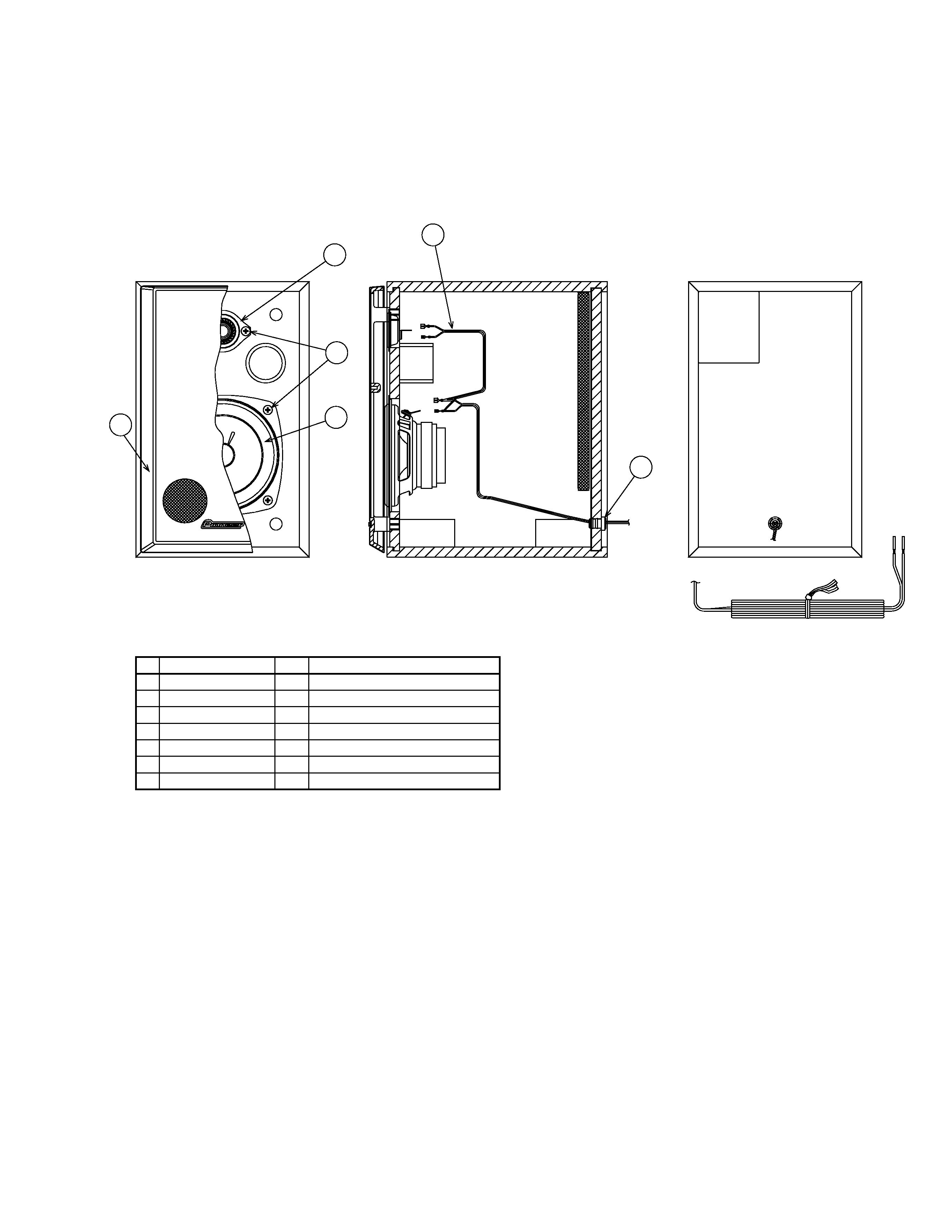
The grille is attached to the cabinet by its bosses applied with
adhesive. To detach it, pry it open by inserting a flat blade
screwdriver into its side. To attach it, apply adhesive to the
holes on the baffle. Then press it to the baffle.
The woofer is attached to the baffle by 4 external screws.
To detach it, unfasten those screws. To detach it, first
remove the grille. Then remove the woofer. When attaching
it, face its terminal upward.
The tweeter is attached to the baffle by 2 external screws. To
detach it, unfasten those screws. To detach it, first remove
the grille. Then remove the tweeter. When attaching it, face
its terminal downward.
The cord stopper is attached to the back board by press-
fitting. To detach it, pull it while rotating it by the radio
pincers