ORDER NO.
PIONEER CORPORATION 4-1, Meguro 1-chome, Meguro-ku, Tokyo 153-8654, Japan
PIONEER ELECTRONICS (USA) INC. P.O. Box 1760, Long Beach, CA 90801-1760, U.S.A.
PIONEER EUROPE NV Haven 1087, Keetberglaan 1, 9120 Melsele, Belgium
PIONEER ELECTRONICS ASIACENTRE PTE. LTD. 253 Alexandra Road, #04-01, Singapore 159936
PIONEER CORPORATION 2007
S-LX70-LR
RRV3697
SPEAKER SYSTEM
S-LX70-LR
XTW/E
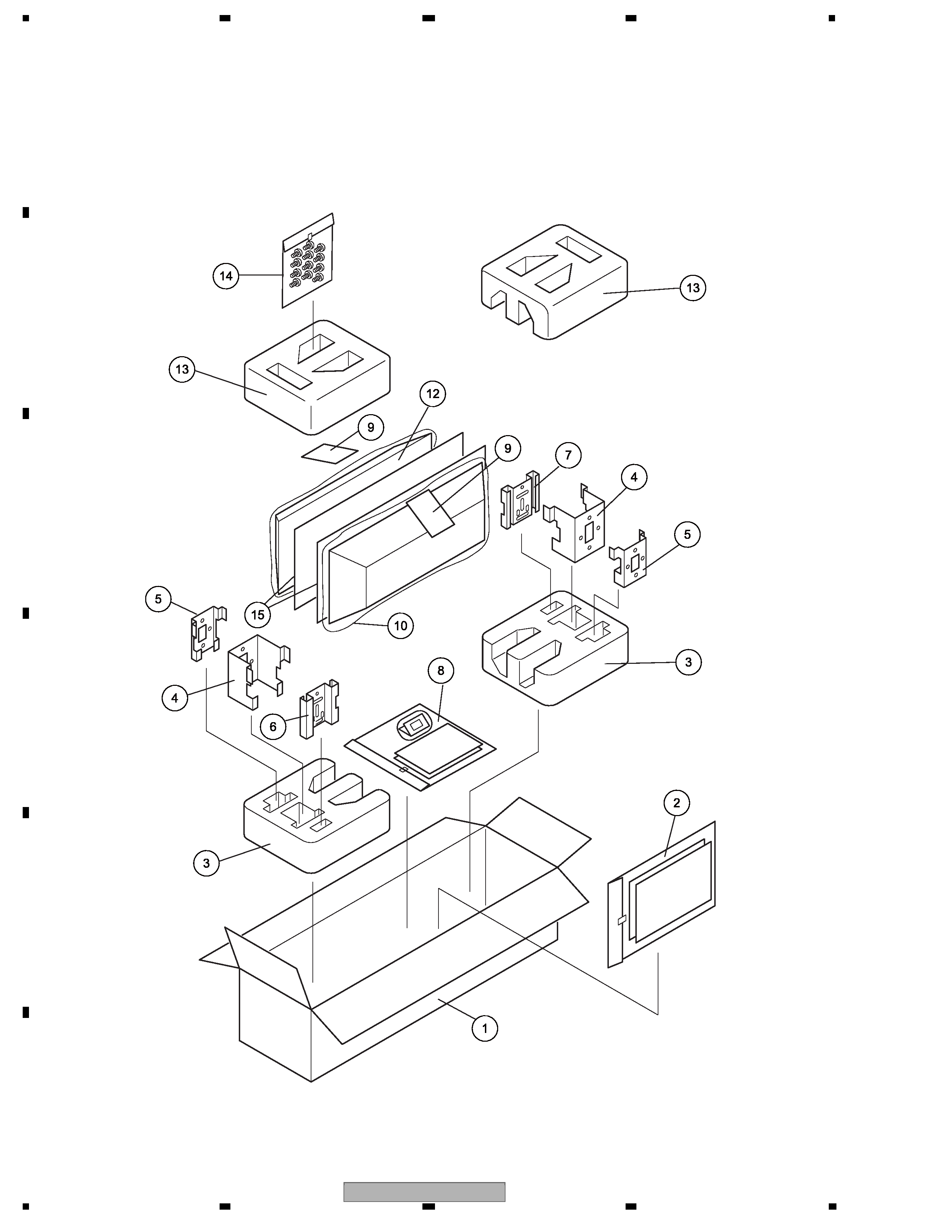
1. REASSEMBLY AND DISASSEMBLY PRECAUTIONS
1.1 GRILLE
· The grille is attached to the cabinet with catches and adhesive.
To remove the grille, use a thin, rigid object, such as a flathead
screwdriver or metal ruler, to pry it off, being careful not to
damage its acrylic coating. To reattach the grille, apply adhesive to
the catches and then press the grille firmly to the cabinet.
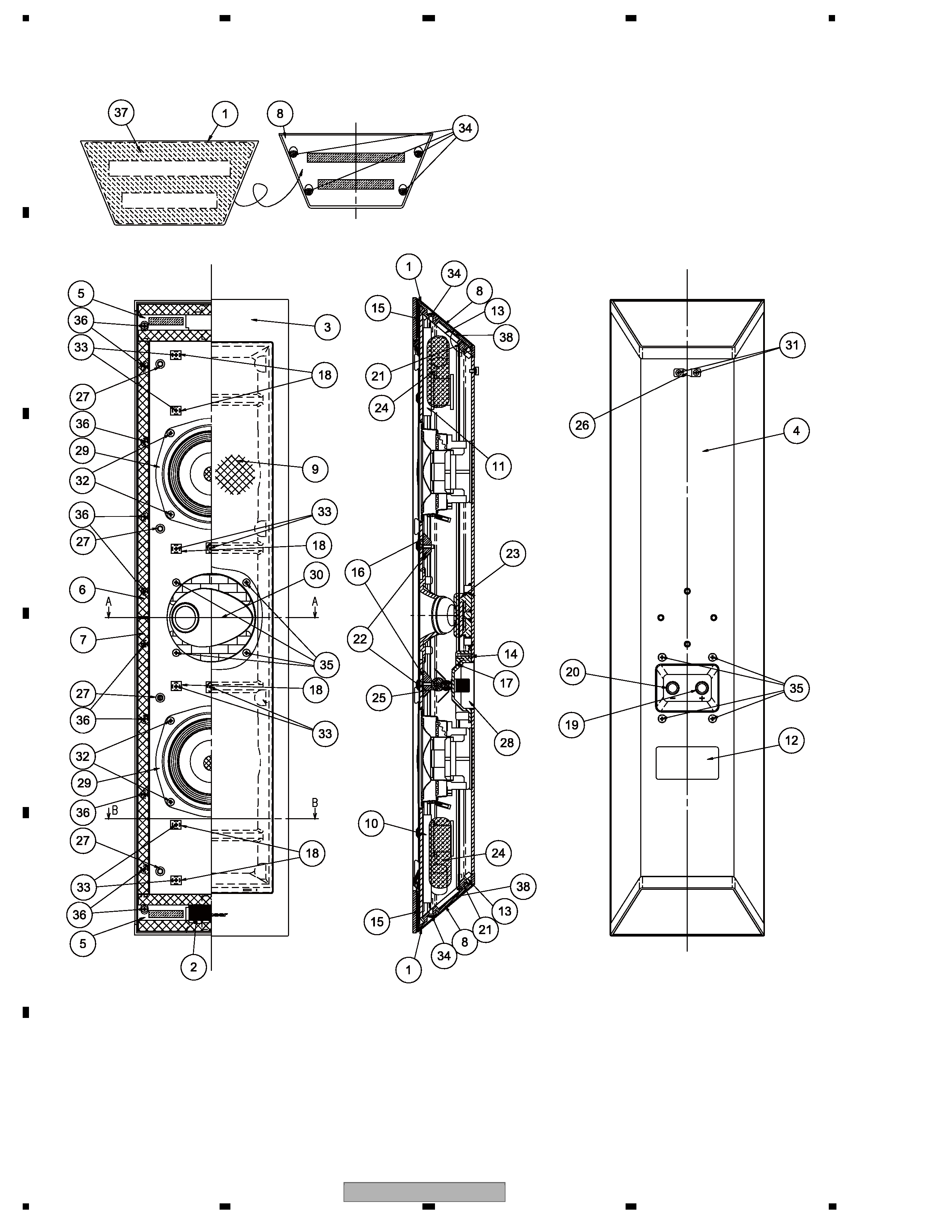
1.2 WOOFER
· Each woofer is attached to the cabinet with 4 screws accessible
from the outside. To remove the woofer, remove these screws. To
reassemble, make sure that the terminal plate of the speaker unit
faces to the lower .
1.3 TWEETER
1. Remove the upper woofer.
2. Remove the packing (SEC2186) between the upper woofer and
the tweeter.
Note: As packing cannot be reused, procure new packing (SEC2186)
for reassembly.
3. Remove the 3 screws. Then pass your hand through the hole for
the woofer and pull out the reinforcing plate.
4. Remove the 4 screws from the tweeter, then pull the tweeter out
through the hole for the woofer. To reinstall the tweeter, place it
so that its terminal plate faces to the upper. Reattach the tweeter
so that the opening of the horn faces left-side and right-side.
The part numbers of the tweeter for L ch and R ch are different.
Be careful in the tweeter installation.
The opening of the horn face becomes the reverse direction
when it attaches a tweeter for L ch and R ch in reverse.
1.4 NETWORK ASSY
1. The Network Assy for the tweeter is located at the upper of upper
woofer, and the Network Assy for the woofer is located at the
lower of the lower woofer.
2. As the screws are covered by packing, before removing the
Network Assy remove the packing first, then remove the woofer.
As packing cannot be reused, procure new packing (SEC2186)
for reassembly.
3. Each Network Assy is attached to the inside of the cabinet with 4
screws accessible from the outside.
4. Pass your hand through the hole for the woofer and securely hold
the Network Assy in place while removing the 4 screws. Pull the
Network Assy out through the hole for the woofer.
T-ZZR NOV. 2007 Printed in Japan