ORDER NO.
PIONEER CORPORATION 4-1, Meguro 1-chome, Meguro-ku, Tokyo 153-8654, Japan
PIONEER ELECTRONICS SERVICE, INC. P.O. Box 1760, Long Beach, CA 90801-1760, U.S.A.
PIONEER EUROPE NV Haven 1087, Keetberglaan 1, 9120 Melsele, Belgium
PIONEER ELECTRONICS ASIACENTRE PTE. LTD. 253 Alexandra Road, #04-01, Singapore 159936
PIONEER CORPORATION 2000
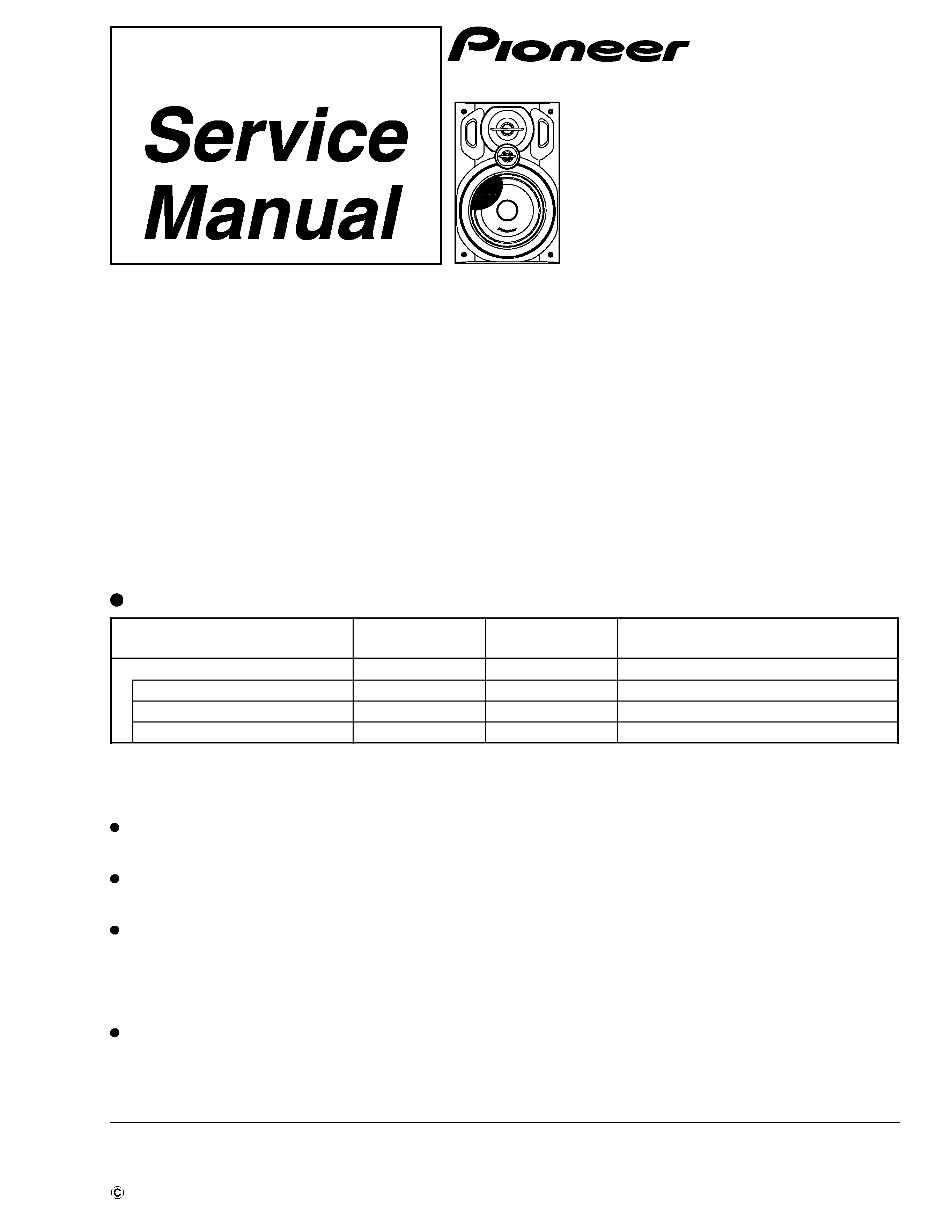
SPEAKER SYSTEM
RRV2394
TZZK OCT. 2000 Printed in Japan
S-LA21
XCN/E
FOR PRECAUTION OF
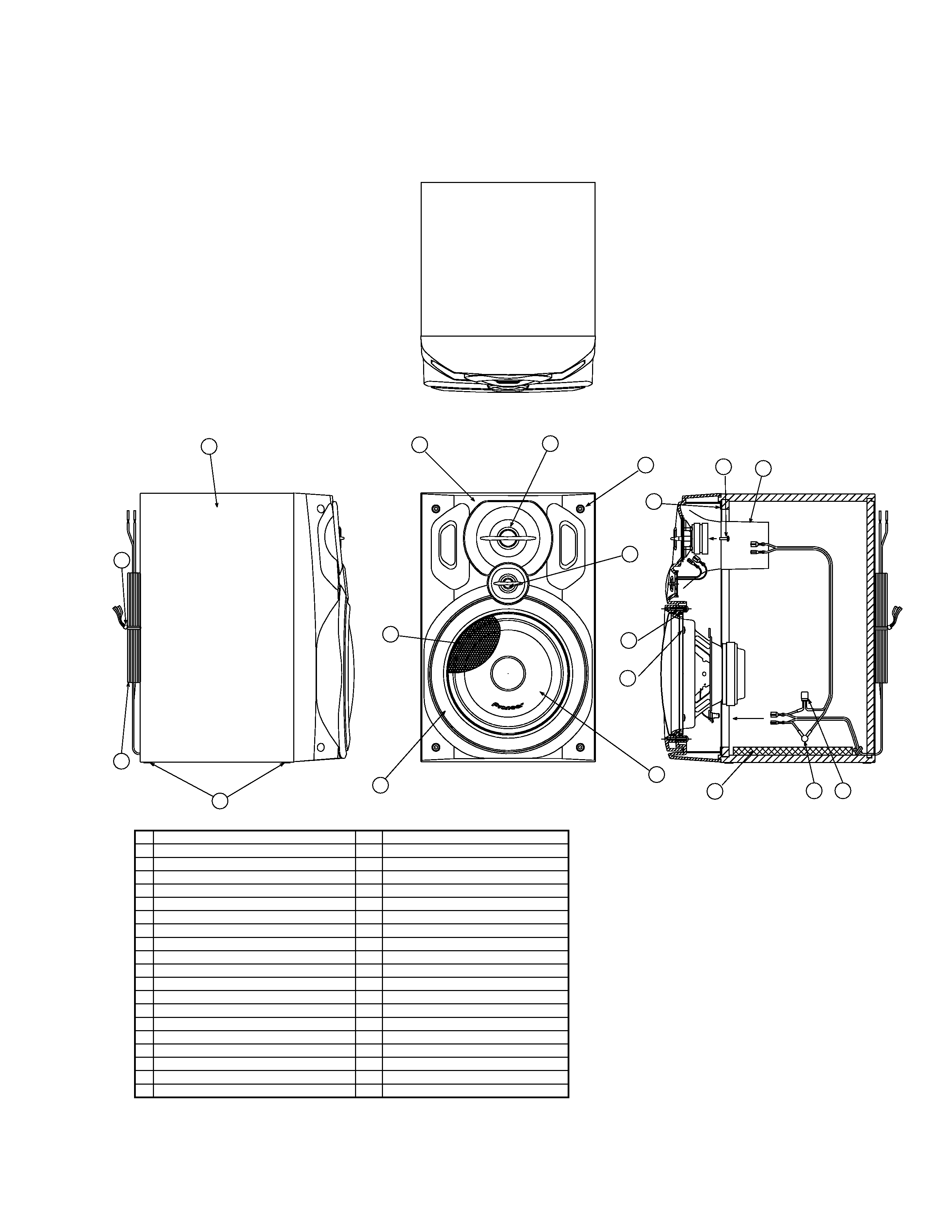
REASSEMBLY AND DISASSEMBLY
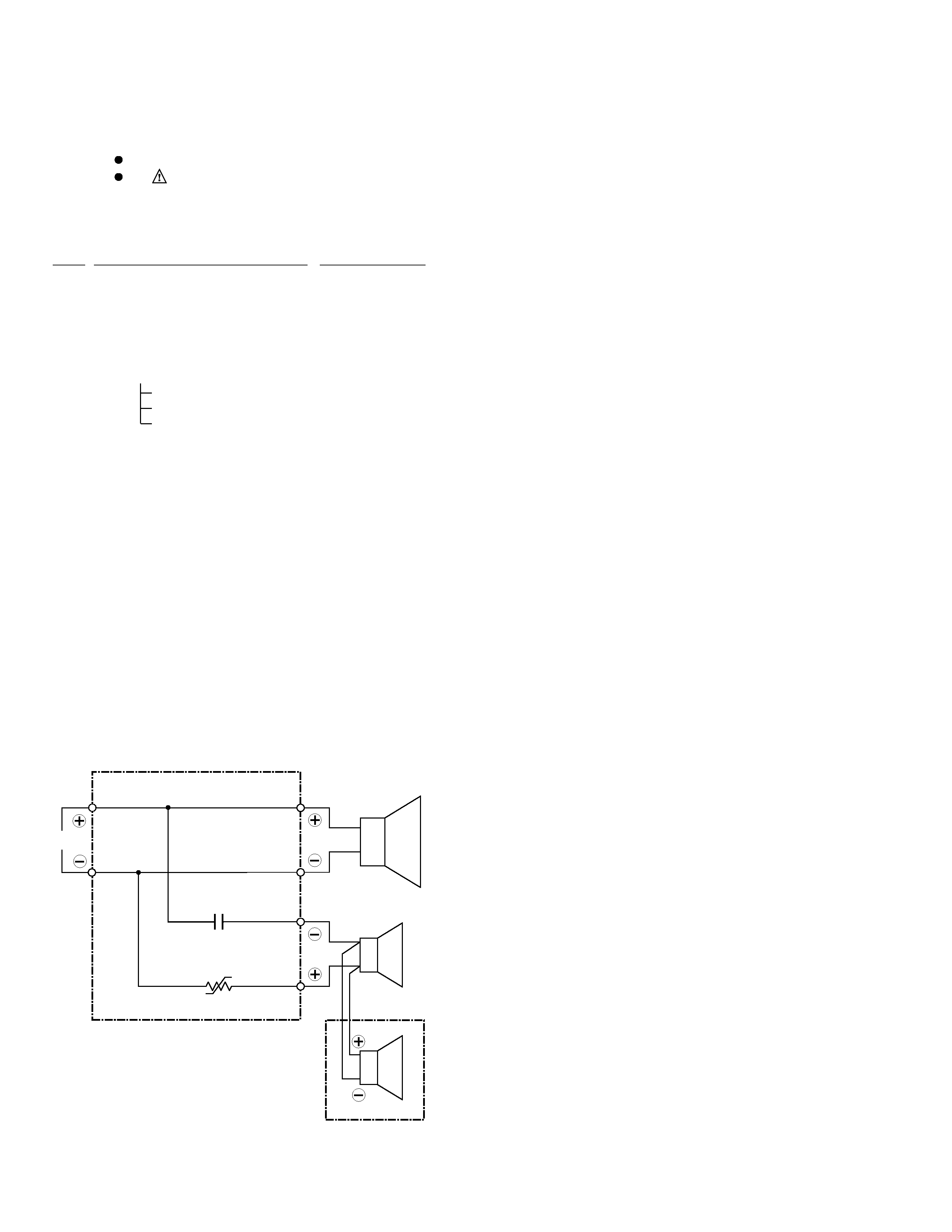
The woofer is attached to the baffle by 4 internal screws. To
detach it, unfasten those screws.
The midrange is attached to the baffle by 2 internal screws. To
detach it, unfasten those screws.
The tweeter is attached to the baffle by a two sided tape which
peels off the separator. In addition, the outer part is fixed with a
bond.
The tweeter cannot be detached. When exchange the tweeter, do
it with the speaker panel assy.
Speaker Ring and Speaker Grille (Panching Net) is attached to
the baffle by 4 internal screws. To detach it, unfasten those
screws. To detach Speaker Grille (Panching Net), first remove
Speaker Ring. Then remove Speaker Grille (Panching Net).
This product is component of system.
Component
Model
Service manual
Remarks
COMPACT MINI COMPONENT
X-LA21
RRV2370
STEREO CD TUNER
XC-LA21
RRV2392
STEREO POWER AMPLIFIER
M-LA21
RRV2393
SPEAKER SYSTEM
S-LA21
RRV2394
This manual.