ORDER NO.
PIONEER ELECTRONIC CORPORATION 4-1, Meguro 1-Chome, Meguro-ku, Tokyo 153-8654, Japan
PIONEER ELECTRONICS SERVICE, INC. P.O. Box 1760, Long Beach, CA 90801-1760, U.S.A.
PIONEER ELECTRONIC (EUROPE) N.V. Haven 1087, Keetberglaan 1, 9120 Melsele, Belgium
PIONEER ELECTRONICS ASIACENTRE PTE. LTD. 501 Orchard Road, #10-00 Wheelock Place, Singapore 238880
PIONEER ELECTRONIC CORPORATION 1998
RRV1989
T-ZZW AUG. 1998 Printed in Japan
FOR PRECAUTION OF
REASSEMBLY AND DISASSEMBLY
The grille is attached to the cabinet by catches. Detach by pull-
ing it toward you.
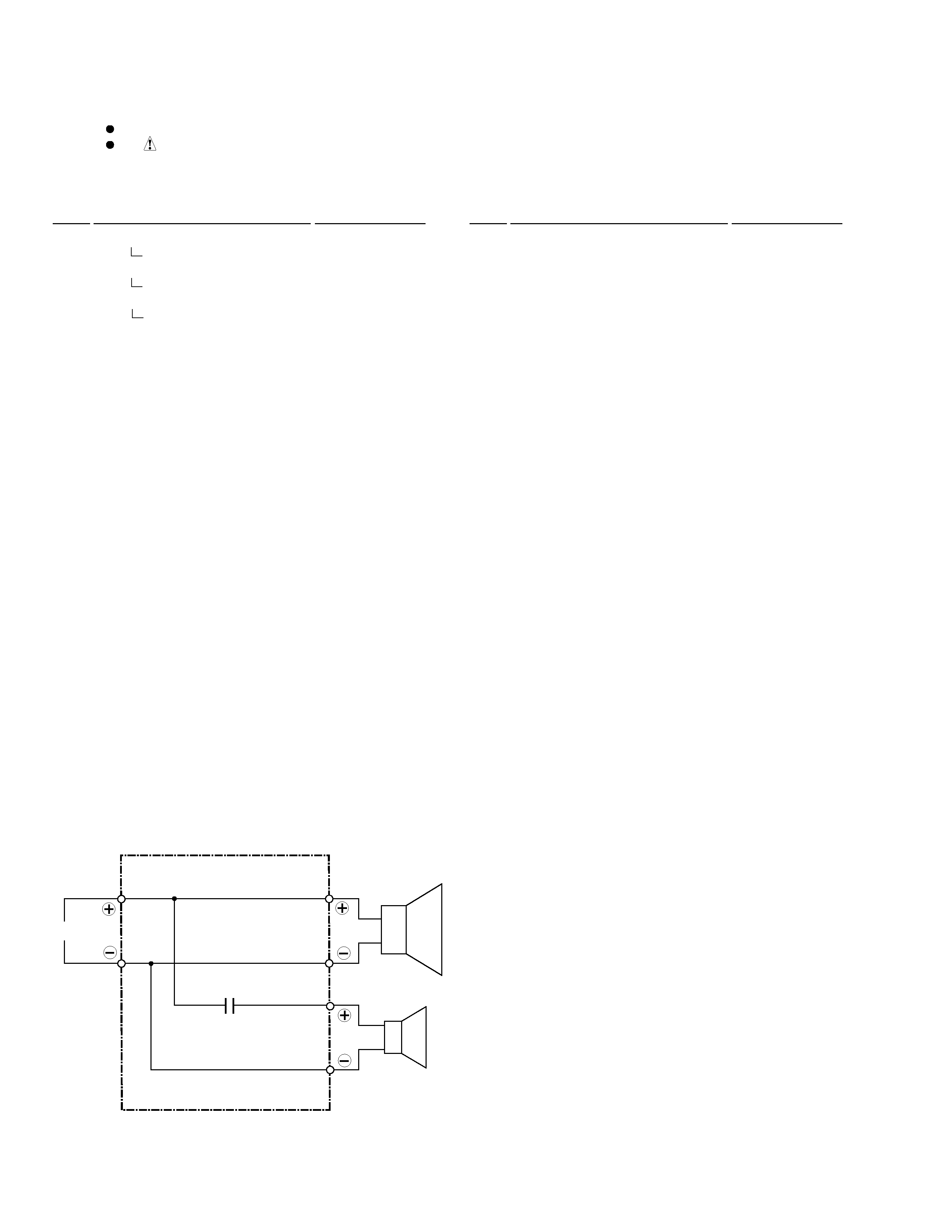
The woofer is attached to the inner baffle by 4 external screws.
To detach it, unfasten those screws. To detach it, first remove
the cosmetic baffle. Then remove the woofer.
When attaching it, fit the boss of the flange into the hole on the
baffle. (Face its terminal upward.)
The tweeter is attached to the inner baffle by 2 external screws.
To detach it, unfasten those screws. To detach it, first remove
the cosmetic baffle. Then remove the tweeter.
When attaching it, fit the boss of the flange into the hole on the
baffle. (Face its terminal lower left.)
This product is component of system.
For the operating instructions, refer to the service manual RRV1997 for XC-L5.
SPEAKER SYSTEM
S-L5V
XE
S-L5V-A XE
S-L5V-K XE
The cosmetic baffle is attached to the inner baffle by its bosses.
To detach it, pry it open by inserting a flat blade screwdriver
into its lower slot. To detach it, first remove the grille. Then
remove the cosmetic baffle.
To attach it, apply acetic vinyl adhesive slightly to the holes on
the inner baffle. Then press it to the inner baffle.