ORDER NO.
PIONEER ELECTRONIC CORPORATION 4-1, Meguro 1-Chome, Meguro-ku, Tokyo 153-8654, Japan
PIONEER ELECTRONICS SERVICE, INC. P.O. Box 1760, Long Beach, CA 90801-1760, U.S.A.
PIONEER ELECTRONIC (EUROPE) N.V. Haven 1087, Keetberglaan 1, 9120 Melsele, Belgium
PIONEER ELECTRONICS ASIACENTRE PTE. LTD. 253 Alexandra Road, #04-01, Singapore 159936
PIONEER ELECTRONIC CORPORATION 1998
RRV2084
T-ZZW DEC. 1998 Printed in Japan
FOR PRECAUTION OF
REASSEMBLY AND DISASSEMBLY
The baffle is attached to the cabinet by its bosses and 4 external
screws. To detach it, first unfasten 4 screws. Then pry it open
holding the side and the cabinet.
The speaker element is attached to the baffle by 4 internal
screws. To detach it, first remove the baffle. Next unfasten
those screws. Then remove the speaker element.
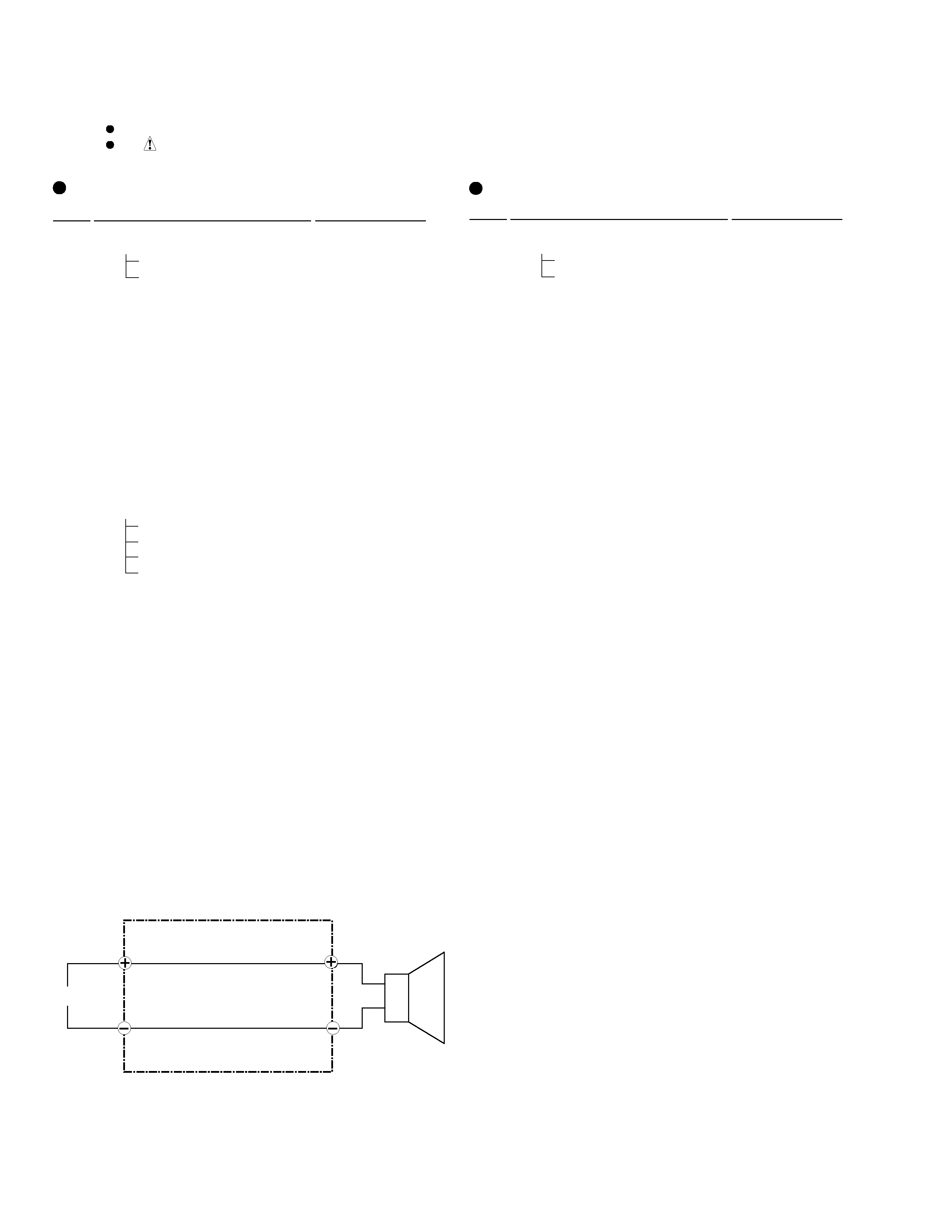
When attaching it, set it on the baffle so that the terminal face
toward the input terminal in cabinet.
The input terminal is attached to the cabinet by 2 internal
screws. To detach it, first remove the baffle. Next unfasten
those screws in cabinet. Then remove the input terminal.
SPEAKER SYSTEM
S-L55-K-LRC
XC
This product is component of system.
For the operating instructions, refer to the service manual RRV2087 for MJ-L5, SP-L5.
S-L55-K-LRC/XC consists of Center Speaker(1pc) and Surround Sound Speaker(2pcs).
65S
This service manual is intended for qualified service technicians; it is not meant for the
casual do-it-yourselfer. Qualified technicians have the necessary test equipment and
tools, and have been trained to properly and safely repair complex products such as
those covered by this manual.
Improperly performed repairs can adversely affect the safety and reliability
of the product and may void the warranty. If you are not qualified to perform the repair
of this product properly and safely, you should not risk trying to do so and refer the
repair to a qualified service technician.
WARNING
This product contains lead in solder and certain electrical parts contain chemicals
which are known to the state of California to cause cancer, birth defects or other
reproductive harm.
Health & Safety Code Section 25249.6 Proposition 65