ORDER NO.
PIONEER CORPORATION 4-1, Meguro 1-chome, Meguro-ku, Tokyo 153-8654, Japan
PIONEER ELECTRONICS SERVICE, INC. P.O. Box 1760, Long Beach, CA 90801-1760, U.S.A.
PIONEER EUROPE NV Haven 1087, Keetberglaan 1, 9120 Melsele, Belgium
PIONEER ELECTRONICS ASIACENTRE PTE. LTD. 253 Alexandra Road, #04-01, Singapore 159936
PIONEER CORPORATION 2000
RRV2335
T-ZZM JULY 2000 Printed in Japan
S-IS21V
XJI/E
S-IS21V XJI/NC
SPEAKER SYSTEM
FOR PRECAUTION OF
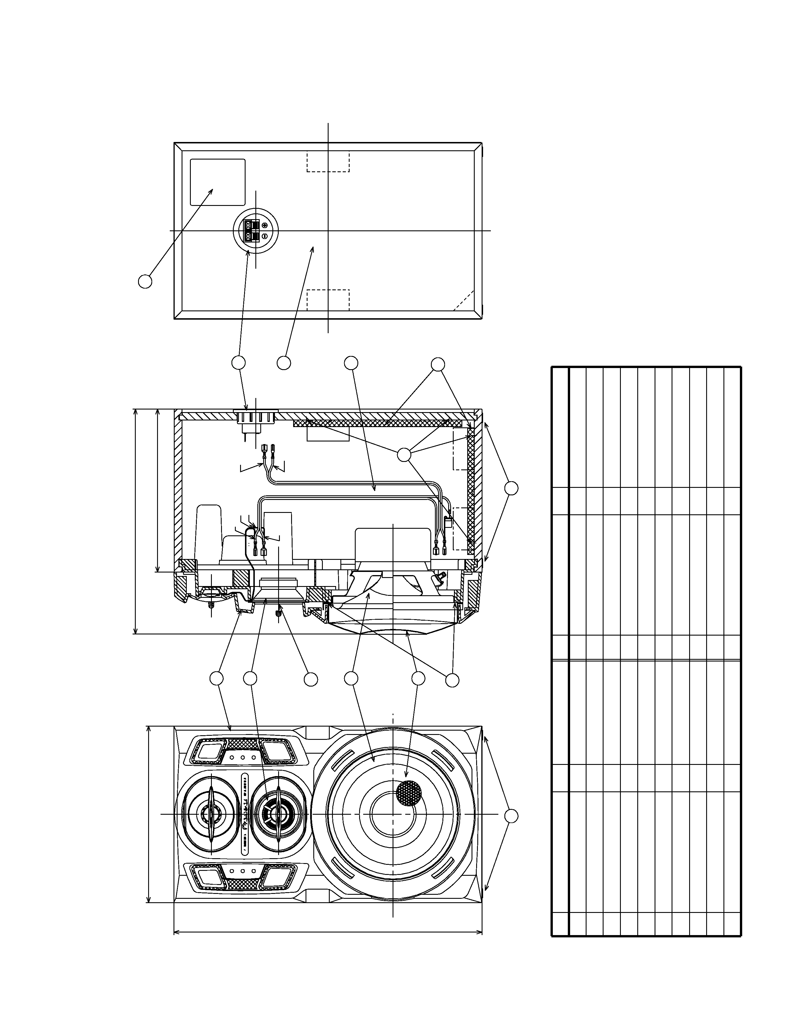
REASSEMBLY AND DISASSEMBLY
This product is component of systems.
The cosmetic baffle is attached to the baffle by its bosses and
press-fitting.
To detach it, pry it open by inserting a flat blade screwdriver
into the cosmetic baffle lower side.
Be careful not to damage the cosmetic baffle and cabinet in
this case.
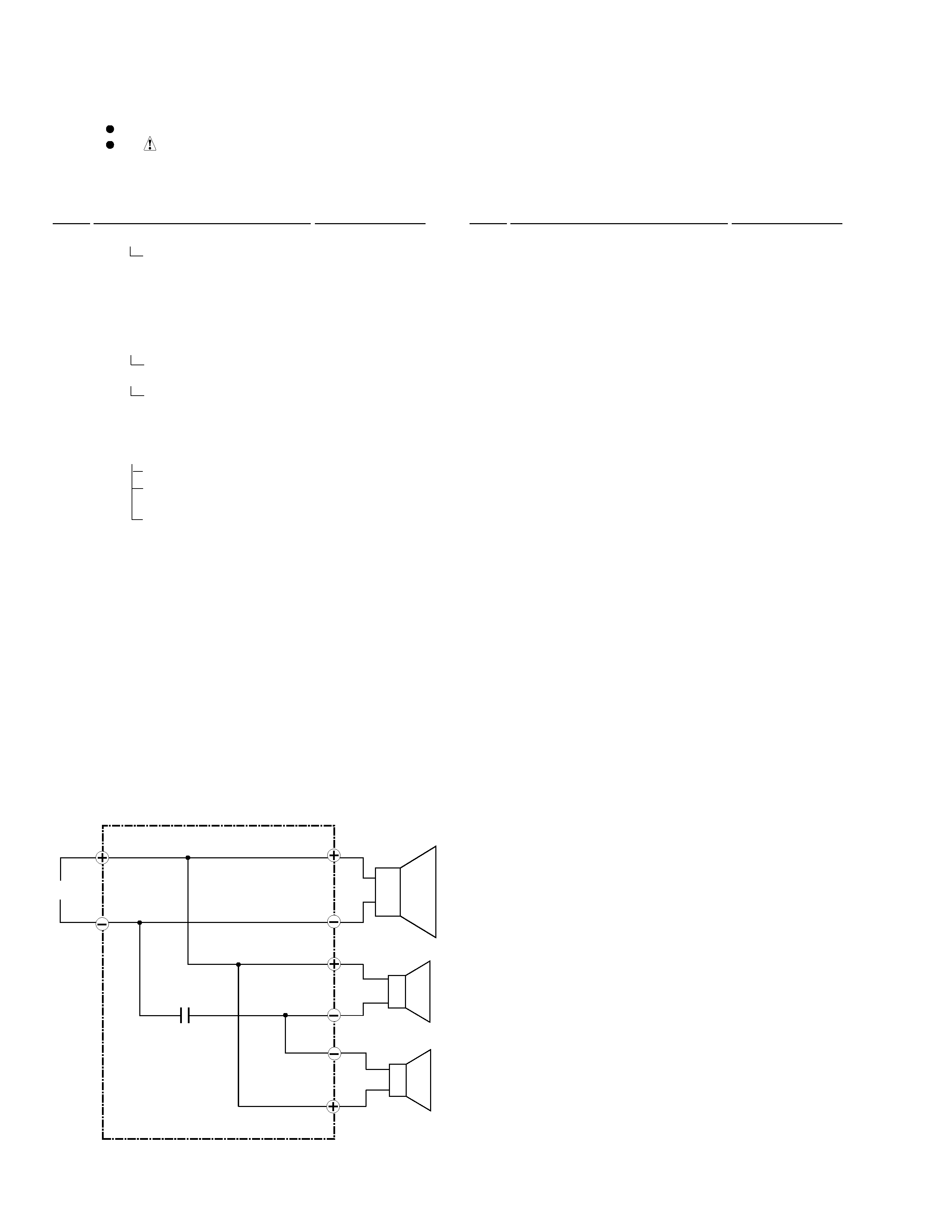
The woofer is attached to the baffle by 4 external screws.
To detach it, first remove the cosmetic baffle.
Next unfasten those screws.
Then remove the woofer.
When attaching it, face its terminal downward.
The midrange is attached to the baffle by 2 external screws.
To detach it, first remove the cosmetic baffle.
Next unfasten those screws.
Then remove the midrange.
When attaching it, face its terminal upward.
The tweeter is attached to the baffle by inserting.
To detach it, first remove the cosmetic baffle.
Next pull it off the baffle.
Then remove the tweeter.
When attaching it, insert the tweeter in the baffle.
System
Service Manual
Remarks
- - - - -
RRV2326
RRV2162
RRV2335
Component
IS-21VCD
XC-IS21V
M-IS21
S-IS21V
COMPACT MINI SYSTEM
STEREO CD/VCD TUNER DECK
STEREO POWER AMPLIFIER
SPEAKER SYSTEM
This service manual